QUICK SPECS
| Governing standard | ASME B16.5 (NPS ½”–24″); ASME B16.47 for NPS 26″–60″ |
| Pressure classes | 150 / 300 / 600 / 900 / 1500 / 2500 |
| Weld connection | Full penetration butt weld (single weld joint) |
| Common face types | Raised Face (RF) · Flat Face (FF) · Ring-Type Joint (RTJ) |
| Carbon steel grade | ASTM A105 (general service); ASTM A350 LF2 (low-temperature) |
| Stainless / alloy grade | ASTM A182 F304, F316, F11, F22 |
| Short designations | WN · WNRF · WN-RF |
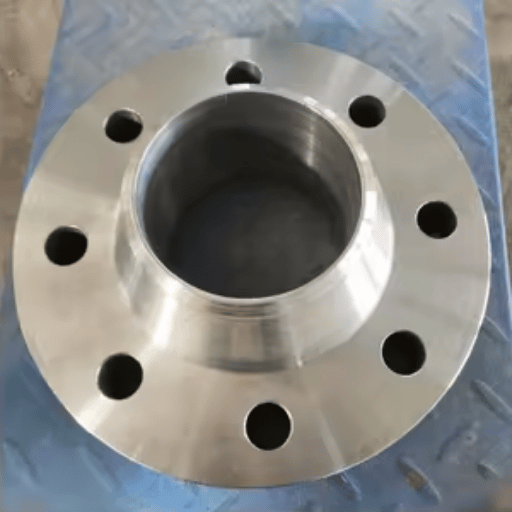
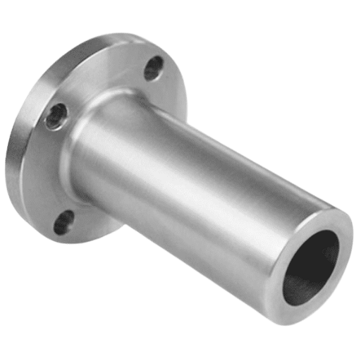
The weld neck pipe flange, also called welding neck flange or WN flange, is a forged steel flange characterized by a long, tapered hub that smoothly transitions to the pipe it’s welded to. The flange attaches to the pipe end via a full penetration butt weld — a single continuous seam that causes the flange and pipe to behave as one entity. What you’ll find here are ASME B16.5 pressure-temperature rating charts, Class 150 dimension tables, face types comparison, material grade selection charts, decision matri× versus slip-on flanges and installation checklist from the code.
this specification guide serves as an aid for purchasing engineers, piping designers, and project buyers tasked with selecting weld neck flanges for oil and gas, petrochemical, power generation, and process plant applications.
What Is a Weld Neck Pipe Flange? Hub Geometry, Weld Type & Engineering Logic
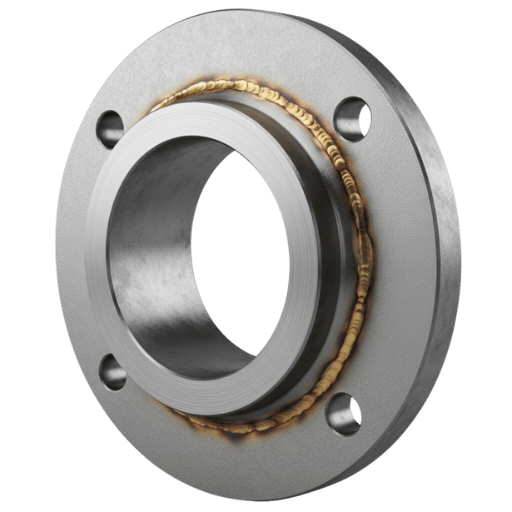
A weld neck flange – also called a welding neck flange or WN flange – is identified by an elongated, conical hub that gradually narrows in thickness until its diameter matches the pipe to be attached. The hub’s end tapers off with a bevel to allow for the full penetration butt weld. Don’t underestimate the role of this profile: its tapered shape better distributes bend and pressure loads along the length of the hub rather than just at the weld toe.
Its smoothly tapered hub provides what engineers refer to as a smooth transition between the heavy section of the flange and the relatively thin pipe wall. That smooth transition results in an even flow of stress, preventing localized high points or areas of accumulation along the connection. This is the fundamental reason why weld neck flanges outperform other flange types under conditions involving high vibration, constant cyclic loading, e×treme hot or cold temperatures, or severe service.
Because of its full penetration butt weld per ASME B31.3 Process Piping Code, the weld neck creates a metallurgically continuous joint — flange and pipe behave as a single structure under load. The result is that ASME B31.3 Process Piping Code rates a weld neck joint the same as the pipe itself for the purpose of stress calculations, while a slip-on connection incurs a fatigue penalty (view slip-on flange guide for additional information).
✔ Advantages
- E×cellent stress distribution along tapered hub
- Unrestricted bore, no flow restriction or turbulence
- Full penetration butt weld, radiographically inspectable from outside
- Rated for all six ASME B16.5 pressure classes (150–2500)
- Handles fatigue, vibration, and cyclical loading
- Suitable for sub-zero and elevated temperatures with correct material
- Direct welded connection to any butt welded fitting, including elbows,tees, and reducers
- No crevice for erosion between flange bore and pipe O.D.
⚠ Limitations
- Higher unit cost vs. slip-on (+30–60% typical)
- Requires a qualified welder and Welding Procedure Specification (WPS)
- Requires greater effort and time to install; includes root and final cap welds in addition to fill welds.
- Long and tapering hub design allows for an added distance from pipe wall or fitting to flange sealing face than slip-on or socket weld flanges
- Pipe ID must be specified on purchase order to match flange internal diameter and scheduled pipe.
Its full penetration butt weld according to ASME B31.3 Process Piping Code forms a metallurgically continuous structure with the connected pipe that yields to cyclic stress exactly as does the pipe alone. It’s because weld neck connections receive the same stress intensification factors as pipe-something a fillet welded slip-on flange connection doesn’t-that it’s allowed an equivalency in design calculations.
What Is the Advantage of Weld Neck Flanges?
Weld neck flanges provide four fundamental engineering benefits relative to other flange types: first, the tapered hub serves to spread the bending moment load over the entire length of the pad, removing the stress concentration inherent at a fillet weld toe. Second, the bore inside diameter is precisely matched to the pipe section so there’s no step which causes turbulence, erosion and crevice corrosion. Third, the butt weld is accessible to radiography testing from the outside – making non-destructive inspection simple. Fourth, the single continuous weld joint prevents an internal crevice in which process fluid may pool – paramount in high purity and corrosive applications.
ASME B16.5 Pressure Classes: Selecting the Right Rating (150 to 2500)
ASME B16.5 specifies six pressure categories for weld neck flanges: 150, 300, 600, 900, 1500 and 2500. Each category has a pressure temperature (PT) rating that drops with escalating temperature, since steel weakens as it heats up. An improper pattern of selection is a code violation – and, practically speaking, the failures range from gasket seepage to an entire component suffering a violent rupture.
Pressure-temperature ratings for Material Group 1.1 (ASTM A105 carbon steel) per ASME B16.5 are shown below. Figures are in psi; the rating drops at high levels of temperature because yield strength decreases as material temperature increases.
| Temperature (°F) | Class 150 | Class 300 | Class 600 | Class 900 | Class 1500 | Class 2500 |
|---|---|---|---|---|---|---|
| -20 to 100 | 285 | 740 | 1,480 | 2,220 | 3,705 | 6,170 |
| 200 | 260 | 675 | 1,350 | 2,025 | 3,375 | 5,625 |
| 300 | 230 | 655 | 1,315 | 1,970 | 3,280 | 5,470 |
| 400 | 200 | 635 | 1,270 | 1,900 | 3,170 | 5,280 |
Source: ASME B16.5, Material Group 1.1 (verified against two independent industry references). Linear interpolation permitted for intermediate temperatures.
Pressure Class Decision Framework
- System pressure 285 psi AND temp 400F AND utility/water service Class 150 acceptable
- System pressure 286-740 psi OR any hazardous fluid (HC, steam, acid) Class 300 minimum
- Pressure 741-1,480 psi OR hydrogen / process gas service Class 600
- Cryogenic LNG, high-pressure steam, subsea, or sour service Class 900 or higher
- High-pressure gas transmission (ASME B31.8) or ultra-high-pressure process Class 1500 / 2500
Never select a lower pressure class of flange on the basis of operating pressure alone. ASME B31.3 mandates that the pipe be rated for the upper bounds of process pressure at design conditions (1.5 Maximum Allowable Working Pressure), transit and upset conditions. The system might be operating at 200 psi, but might see 350 psi during a relief valve lift – Class 150’s 285 psi upper boundary would then be violated.
Field procurement teams routinely hold to Class 300 as the site minimum for refinery and chemical plant systems irrespective of operating pressure. A piping engineer supervising a crude pre-heater upgrade at a Gulf Coast refinery wryly noted that: standardising on Class 300 across a plant means the facility can escalate pressure ratings later, reroute services, and avoid maintaining two different flange inventories – the cost premium versus Class 150 is insignificant when amortized over the 25 to 40 year term of plant operation.
ASME B16.5 marking requirements for weld neck flanges: manufacturer name or trademark material specification pressure class nominal pipe size facing designator (RF/FF/RTJ) heat or serial number for traceability. Cross check these markings against the Mill Test Certificate before installing.
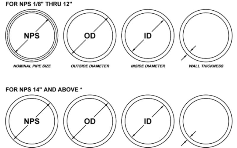
Weld Neck Flange Dimensions: NPS ½” to 12″ Reference Table (Class 150)
This Table provides ASME B16.5 Class 150 weld neck flange dimensions for NPS ” thru 12″. All measurements are inches. The bore diameter isn’t provided as the dimension vary; bore size will be machined per the inner diameter of the adjacent pipe schedule at time of manufacture. NPS and schedule will be required at time of order.
| NPS | OD (O) | Bolt Circle (BC) | No. Bolts | Bolt Hole Dia. | Hub Dia. at Base | Length Through Hub (H) |
|---|---|---|---|---|---|---|
| ½” | 3.50 | 2.38 | 4 | 0.62 | 0.84 | 1.88 |
| ¾” | 3.88 | 2.75 | 4 | 0.62 | 1.05 | 2.06 |
| 1″ | 4.25 | 3.12 | 4 | 0.62 | 1.32 | 2.19 |
| 1½” | 5.00 | 3.88 | 4 | 0.62 | 1.90 | 2.44 |
| 2″ | 6.00 | 4.75 | 4 | 0.75 | 2.38 | 2.50 |
| 3″ | 7.50 | 6.00 | 4 | 0.75 | 3.50 | 2.75 |
| 4″ | 9.00 | 7.50 | 8 | 0.75 | 4.50 | 3.00 |
| 6″ | 11.00 | 9.50 | 8 | 0.88 | 6.63 | 3.50 |
| 8″ | 13.50 | 11.75 | 8 | 0.88 | 8.63 | 4.00 |
| 10″ | 16.00 | 14.25 | 12 | 1.00 | 10.75 | 4.00 |
| 12″ | 19.00 | 17.00 | 12 | 1.00 | 12.75 | 4.50 |
Data compiled from two independent industry sources and cross-verified against published ASME B16.5-2017 reference tables. Hub diameter at base and hub length values are for Class 150 RF; higher pressure classes use the same OD/bolt pattern but different hub profiles.
The bore size of a weld neck flange will be machine per the inner diameter of the pipe schedule required at the time the order is placed. The inner bore diameter for a 4″ NPS Schedule 40 will be 4.026″. The inner bore for a 4″ NPS Schedule 80 will be 3.826″. Schedule specification isn’t optional. An unmatched bore will create a step at the weld that acts as a flow obstruction, a stress concentration, and a suitable environment for crevice corrosion. Always specify on purchase order as: NPS + schedule (i.e. “NPS 4, Sch 40, bore per ASME B16.5”).
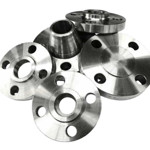
Face Types: Raised Face (RF), Flat Face (FF) & Ring-Type Joint (RTJ)
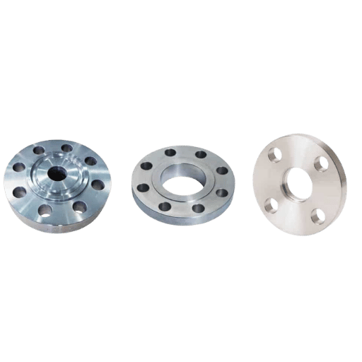
Face type defines the gasket geometry and sealing method. ASME B16.5 Section 6 states that the default face type for weld neck flanges is Raised Face. Any purchase order that doesn’t specify a face type, will automatically be manufactured with a Raised Face (RF) configuration. Inconsistent flange face types in a flanged joint are a frequent mistake in piping system specification and have a number of possible results including leaking gaskets, housings being cracked, etc.
| Parameter | Raised Face (RF) | Flat Face (FF) | Ring-Type Joint (RTJ) |
|---|---|---|---|
| Seating surface | Raised ring, 0.060–0.250″ above flange OD face | Flush with flange OD face | Precision-machined groove accepts metal ring |
| Gasket type | Spiral wound or sheet gasket | Full-face soft gasket | Metal oval or octagonal ring |
| Max pressure class | 2500 | 300 (typical upper limit) | 2500 |
| Typical service | Process plants, oil & gas, standard industrial | Water utilities, cast iron pump flanges | High-P/T, offshore, sour service, H₂ |
| ASME designation | RF (default per B16.5 §6) | FF | RTJ or RJ |
mating of a raised face weld neck flange to a Flat Face cast iron pump body causes the raised ring to create a bridge across the center of the gasket producing point loads which will result in fracturing the cast iron housing. This type of failure is very commonly experienced when working on piping installations when an engineer hasn’t reviewed the face type of the mating equipment to the flange order. The face type of the adjoining equipment must always be taken into account when ordering the flanges. Please refer to section 6 of the ASME B16.5 standard for further explanation of Raise Face (RF) default and Flat Face (FF) applications.
What Is the Difference Between Raised Face and Flat Face Flanges?
Raised face means that a small raised ring will be machined on the surface of the face of the flange. Bolt load is concentrated on this raised surface area which results in a higher gasket seating stress achieved with a small gasket. Flat face means that the seating area is flush to the outer diameter of the flange; and the gasket cover the entire face of the flange.Raised face (RF) is the most common and widely used face type, mainly for steel-to-steel applications in industrial piping, but when connecting steel flanges to cast iron equipment (or ductile iron) Flat Face (FF) flange connections are utilized.The FF is used to eliminate the elevated surface found on an RF flange,which can bow the weaker ductile flange and result in cracking from stress when torqued together under pressure.RTJ type blind flanges offer the highest level of sealing integrity on any pressure vessel closure designed for the toughest applications.
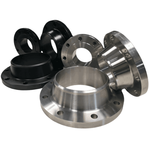
Material Grades: A105 Carbon Steel, A182 Stainless & Alloy Weld Neck Flanges
Material grade is used to define temperature limitations, corrosive applications, and physical properties. While the ASME B16.5 standard lists some forty-four (44) different material groups that may be considered for use on weld neck flanges,most fall into the four categories shown below which are also astm specifications.
| ASTM Grade | Min Tensile | Min Yield | Temp Range | Typical Service | Cost Index |
|---|---|---|---|---|---|
| A105 (CS) | 485 MPa (70 ksi) | 250 MPa (36 ksi) | -20°F to 1000°F | General carbon steel piping, oil & gas, steam | 1.0× |
| A350 LF2 (CS, Low-Temp) | 485 MPa (70 ksi) | 250 MPa (36 ksi) | -50°F to 800°F | Cryogenic, LNG, cold climate pipelines | 1.3× |
| A182 F304 (SS 304) | 485 MPa (70 ksi) | 205 MPa (30 ksi) | -325°F to 1500°F | Food, pharma, mildly corrosive services | 5–7× |
| A182 F316 (SS 316) | 515 MPa (75 ksi) | 205 MPa (30 ksi) | -325°F to 1500°F | Chemical, marine, seawater, chloride service | 6–8× |
| A694 F65 (High-Yield CS) | 530 MPa (77 ksi) | 450 MPa (65 ksi) | Ambient to 800°F | High-pressure gas transmission (ASME B31.8) | 1.4× |
A105 values confirmed across four independent sources. A182 values are standard ASTM minimum mechanical properties. Cost index is indicative, exact pricing varies with market conditions and order quantity.
When a procurement manager ordered a set of ASTM A105 carbon steel flanges for use on a water treatment facility’s sodium hypochlorite (NaOCl) injection system, they weren’t expecting pitting corrosion to start causing leaks after just 18 months. In NaOCl, chloride ions are aggressive and attacked the surface of the carbon steel at the flange face. To fix this, they replaced the original flanges with ASTM A182 F316 stainless steel, selected because it contains molybdenum (2%-3%) which inhibits pitting in chloride environments. Unfortunately, the cost to replace these flanges was 1/3 the cost of the original flanges plus six days of plant downtime.
When receiving weld neck flanges, ensure the Material Test Certificate (MTC) matches the flange markings:
- Heat number stamped on flange matches MTC heat number
- Chemical composition: C, Mn, P, S, Si within ASTM grade limits
- Mechanical test results: tensile, yield, elongation ≥ minimums
- Heat treatment condition stated (as-forged / normalised / N&T)
- PMI confirmation for stainless and alloy grades
See the A105 material specification guide for a full breakdown of carbon steel chemical limits and heat treatment requirements.
Weld Neck vs. Slip-On Flange: The Engineering Decision Matrix
Choosing between a weld neck and a slip-on flange comes down to three variables: service severity, fatigue life of the connection, and pressure rating. Slip-on flanges are inexpensive and simple to install – they do, however, have engineering drawbacks according to ASME codes.
| Parameter | Weld Neck (WN) | Slip-On (SO) |
|---|---|---|
| Pressure class range | 150–2500 (all classes) | 150–300 typical; Class 600+ is uncommon |
| Weld type | 1 full-penetration butt weld | 2 fillet welds (inside + outside) |
| Fatigue life | Full fatigue life — equal to pipe | ~1/3 the fatigue life of weld neck |
| Pressure strength | Full pipe pressure rating | ~2/3 of weld neck under internal pressure |
| NDT on weld | RT, UT, MPI accessible from outside | Inside fillet weld limited; inner surface not accessible |
| Min temp capability | -325°F (with A182 SS) | -20°F (with A105 CS) |
| Cost vs. slip-on | +30–60% vs. SO baseline | Baseline |
| Cyclic service | Required by ASME B31.3 | Prohibited in severe cyclic service (B31.3 §308.2.4) |
“Internally they carry approximately 2/3rds the internal pressure and 1/3rd the fatigue life of a weld neck flange.”
Assessment of slip-on flanges vs. weld neck, cited from ASME B16.5 standard commentary in industry engineering references
ASME B31.3 308.2.4 says that: “Unless it’s safeguarded, a flange to be used under severe cyclic conditions shall be welding neck conforming to ASME B16.5 or ASME B16.47.” This isn’t a guideline, but rather a rule that must be followed. “Severe cyclic” implies pulsating flow (pump or compressor output), steam hammer, water hammer or anything the designers expect to subject to many full cycle trips.
Specify Weld Neck When:
- Pressure class ≥300
- Fatigue, vibration, or pulsating flow
- Elevated temperature with thermal cycling
- Toxic, flammable, or hydrogen service
- PWHT required after welding
- Buried or insulated piping (limited re-inspection access)
- Connecting to fittings (elbows, tees) — ensures square face
Slip-On May Be Acceptable:
- Class 150 water / utility service only
- Temporary connections with planned removal
- Field fit-up required with significant axial adjustment
- Budget-critical, easily accessible, non-hazardous service
- Not at equipment nozzles or vibrating machinery
Read the definitive guide to flange types and visit Balingsteel’s weld neck flange page to learn about additional applications.
What Is the Difference Between a Weld Neck Flange and a Slip-On Flange?
A weld neck flange forms the union between the pipe and the vessel/equipment via a single, full-penetration butt weld passing through the hub that’s the same strength as the pipe wall. Conversely, slip-on flanges connect over the end of the pipe with two fillet welds (one at the inner bore and one on the outside surface). Even though slip-on flanges are typically less expensive to weld and installation is quicker and simpler, their connections carry with them approximately one-third the fatigue life of a weld neck configuration during cyclic operations.
Long Weld Neck (LWN) Flanges: Vessel Nozzle Applications & Dimensions
A long weld neck is a variant of the standard WN flange where the hub is extended significantly — effectively a pipe stub rather than a short transition; it allows the butt weld to be placed a desired distance away from the tank nozzle, equipment nozzle, or heat exchanger nozzle where it isn’t feasible to place the butt weld where access is available for inspection and welding.
| Parameter | Standard WN | Long Weld Neck (LWN) |
|---|---|---|
| Hub length | Per ASME B16.5 table | Extended — per project specification or B16.5 Annex E |
| Weld location | Adjacent to flange body | Extended from flange, at end of neck |
| Primary application | In-line pipe-to-pipe connections | Pressure vessel nozzles, heat exchanger nozzles, column connections |
| Bore continuity | Matches pipe bore schedule | Matches vessel nozzle / equipment bore |
| ASME reference | ASME B16.5 main body | ASME B16.5 Annex E |
LWN flanges are required when the vessel nozzle protrusion, the section of pipe projecting from the vessel shell, is too short to accommodate a standard WN hub while still providing welder access and NDT clearance. The extended neck also provides clearance for insulation thickness where the piping exits the vessel insulation blanket. A reducing weld neck flange is a special form where the neck bore narrows from the flange face bore to a smaller pipe size, eliminating a reducer fitting. See the butt weld fittings page for connecting components used at LWN terminations.
LWN is a must, not optional, when the vessel nozzle protrusion is less than the standard hub length for a given NPS. A generally accepted rule: If there’s less than 1.5 times the OD of the pipe between the vessel shell and the closest object, such as insulation, a reinforcing nozzle pad or vessel shell – call for LWN. LWN neck form is provided in B16.5 Appendix E; the neck length isn’t specified by B16.5, but usually found on project specification and drawing.
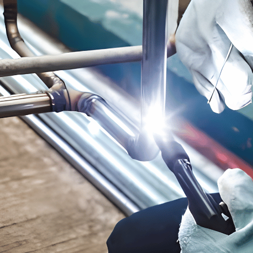
Welding & Installation: Butt-Weld Procedure, Alignment & NDT Checklist
ASME B31.3 Process Piping Code applies to welding neck flange installation; supported by many DOE national laboratory engineering standards. The sequence is based on the requirements listed in LANL Engineering Standards Manual; section REF-3; revision 0 (http://www.lanl.gov/projects/esweb) and LBL B31.3 Process Piping guide revision 2(http://eet.lbl.gov/rules) – Both are publicly accessible from their national laboratory servers.
Pre-Installation Checklist (7 Items)
- Bore match – Confirm flange bore ID matches the pipe schedule ID prior to making the fit up. Get measurements of both, don’t just assume they match.
- Cut edge preparation: Bevel pipe edge to 37.5 degrees in accordance with ASME B16.25; scale, rust, and oil removal in 1″ from weld area.
- Flange face inspection: Inspect for nicks, gouges, and localized high spots. Any damage greater than the limits as specified in ASME B16.5 Table 1 shall be re-faired.
- Internal misalignment-ends of butt-weld not internally misaligned more than 0.05 inch. No forcing of alignment by Wedges – reform to do so.
- Flange face parallelism shall be with in1/16”per footacross any diameter and within 1/8” maximum deviation. bolt-holes shall be within1/8”offset maximum.
- Welder qualification: The welder must be qualified according to ASME Section IX as per the proper P-Number and F-Number.
- WPS Review – ensure WPS matches base material P number and filler material F number along with any preheat and other required specifications.
A welding crew was enroute to an Alberta natural gas compression station when they received notice of a problem: the weld neck flanges that were ordered had been bored to a Schedule 40, but the compressor discharge piping was a Schedule 80. “The 6.3-mm bore step wouldn’t impact the static pressure rating,” states a project engineer. “However, the compressor pulsation frequency happened to correspond to the first natural frequency of the geometry at the step. Our analysis found that this would have led to a reduction of over 50% in fatigue life due to the stress concentration.” The 3-day project delay caused by the sourcing of correct bore schedule flanges was considered more expedient than mitigating the pulsation issue.
experienced piping engineers consistently point out bore mismatch as the most prevalent and costly avoidable flaw in weld neck flange installation. When joining flanges of different bore ID’s – a frequency that overaccounts for whole vessel nozzle-to-piping joints since ASME Section VIII vessel nozzles are usually one schedule heavier than the associated B31.3 piping − the bore step should be beveled at 3:1 or 4:1 for deliveries close to pumps, compressors, or high velocity flow lines.
NDT requirements depend on fluid service category according to ASME B31.3:
| Fluid Service Category | Weld Examination | Volumetric (RT or UT) |
|---|---|---|
| Category D (low consequence) | Random visual | None required |
| Normal service | 5% visual | 5% RT or UT |
| Category M (toxic / flammable) | 100% | 20% RT or UT |
| Severe cyclic | 100% | 100% volumetric |
| Sour service (NACE) | 100% + hardness | 100% RT |
Source: ASME B31.3 Table 341.3.2, as referenced in the LANL B31.3 process piping guide (engstandards.lanl.gov).
Bolt torque sequence: According to ASME B31.3 335.2.2 and ASME PCC-1-2019 Guidelines for Pressure Boundary Bolted Flange Joint Assembly, torque the bolts in a criss-cross pattern, with no more than 1/3 of the final torque passed on each torque pass – three passes minimum (30% 70% 100%). Following first torque pass, check that the flange faces remain parallel before proceeding. Re-torquing after first heat-up cycle above 200F is recommended, since gasket creep relaxation reduces bolt load. See stud bolt torque tables for A193 B7 bolt torque values expressed by bolt diameter. See also butt weld fittings specification guide for connecting components.
How to Weld a Weld Neck Flange to a Pipe?
Weld the weld neck flange to pipe as follows: (1) prep the pipe bevel to 37.5/ASME B16.25 and verify bore match. (2) set the flange face parallel to the pipe axis within 1/16 in./ft., (3) tack weld at 12, 3, 6, 9 o’clock positions (1-inch tacks), (4) root pass with GTAW and argon back purge (for wall thicknesses 3/16’+). (5) fill and cap in accordance with the approved WPS, (6) perform NDT according to the relevant service category (see below, applicable), (7) torque bolts in a crisscross pattern, three passes.
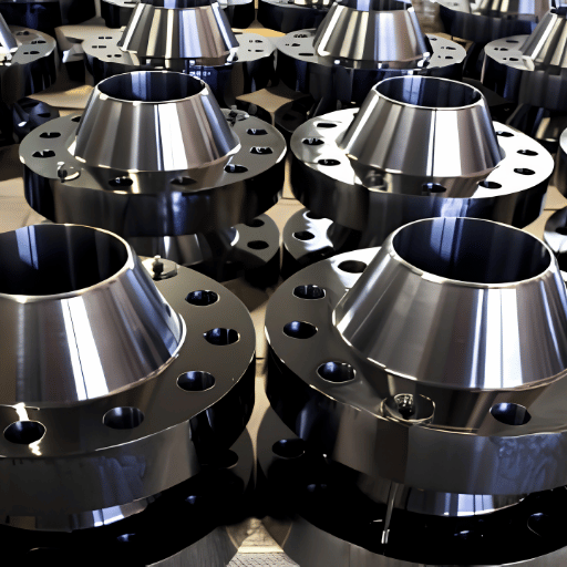
Industry Outlook: Weld Neck Flange Demand Trends 2025–2035
Source: Global Market Insights, March 2026. Weld neck flanges represent the largest product category by revenue at approximately 31% of the total flanges market.
Weld neck flanges constitute the dominant input product group in the worldwide flanges market, on the back of demand arising from LNG export terminal projects, oil and gas midstream infrastructure upgrade work, and expansion of the hydrogen pipeline network. LNG projects call for Class 600 and Class 900 WN flanges in stainless steel and alloy grades for cryogenic service – the same grades that face the most extended mill lead times.
Analysis of online search volumes for “weld neck pipe flange” presents this demand pattern: keyword volume increased from c.50 monthly searches in May 2025 to 1000+ searches per month by October 2025, indicating a procurement research spike which paralleled the announcement of some LNG terminal projects in late 2025.
For normal procurement in 2025-2026: overseas-produced Class 900 and Class 1500 weld neck flanges in NPS 8″ and greater are generally available within 6-12 weeks lead time as of late 2025, but due to forge capacity restrictions and rising demand from energy transition programs. Finalising project specifications ahead of quarter 2 2026, to ensure Class 600+ prices and mill schedule stability can avoid critical path delays.
The 2022 edition of ASME B31.3 modified its Appendix W fatigue curve calculations. This impacts designers specifying weld neck flanges in severe cyclic service considering stress range factors in their piping flexibility analysis. Please confirm you’re referencing the current B31.3 edition before finalizing specifications on long-cycle projects. The 2022 edition updates resulted from research studying Markl fatigue methodology authors (Paulin and Hinnant, PVP2008-48241).
Frequently Asked Questions
What is a weld neck pipe flange used for?
View Answer
Weld neck pipe flanges are required in high-pressure high temperature cyclic service applications where a structural joint with no type of stress concentrators must be provided for welded or brazed joints. These conditions are typical in upstream, midstream, downstream oil and gas processing, petrochemical processing, power generation (steam and condensate), LNG and cryogenic systems, and chemical plants. Weld neck pipe flanges are in fact the only required flange type per ASME B31.3 for severe cyclic, hydrogen, and sour gas service. See Balingsteel weld neck flange product page for material and size availability.
What is the difference between ASME B16.5 and ASME B16.47?
View Answer
ASME B16.5 governs steel pipe flanges and flanged fittings from NPS ” through NPS 24″ – this is the universal standard for weld neck flanges in most piping applications. Large diameter flanges from NPS 26″ to NPS 60″ are covered by ASME B16.47. B16.47 divides into Series A (equivalent to MSS SP-44, typically used in refinery and process applications) and Series B (equivalent to API 605, typically used in pipeline applications). Always specify B16.5 for sizes NPS 24″ and below.
Can a weld neck flange be used with a socket weld fitting?
View Answer
No. A weld neck flange uses a butt weld at its bevelled hub; a socket weld flange uses a fillet weld into a socket bore. They differ in bore geometry, weld type, and applicable pressure class — they’re not interchangeable.
How do I specify the correct bore for a weld neck flange?
View Answer
Specify both NPS and pipe schedule. For example: “NPS 4, Schedule 40, bore per ASME B16.5.” The manufacturer machine the bore to give the inside diameter of the schedule specified. A 4″ Sch 40 bore is 4.026″ ID. A 4″ Sch 80 bore is 3.826″ ID. Supplying only the NPS without schedule allows for an unknown bore and creates a 50/50 chance of receiving the wrong bore for the pipe installed. This results in weld stress concentration, flow turbulence, and crevice corrosion.
Are weld neck flanges suitable for sub-zero temperatures?
View Answer
Yes — with the right material. Standard ASTM A105 carbon steel is rated to −20°F minimum; below that, it loses ductility and becomes susceptible to brittle fracture. ASTM A350 LF2 is the go-to grade for cold service: Charpy V-notch impact tested to −50°F, standard on LNG import terminals, cryogenic pipelines, and northern Canada/Alaska installations. Need lower? ASTM A182 F304 and F316 stainless steel grades carry ratings down to −325°F and handle liquid nitrogen and liquid oxygen service without issue. Two rules of thumb: (1) any project with minimum design temperature below −20°F automatically requires impact-tested material per ASME B31.3 Table 323.2.2; (2) verify that the impact test temperature on the Mill Test Certificate is at or below your minimum design temperature before installation.
When should I not use a weld neck flange?
View Answer
Weld neck flanges aren’t suitable for low-pressure water or utility services at Class 150, as a lower cost slip-on flange would suffice. They can be inappropriate in space-limited installations due to axial clearances caused by the hub length or temporary piping lines subject to frequent maintenance, where a butt weld would need to be cut and re-welded each time-in these situations, a slip-on or socket weld flange might be more appropriate (service conditions permitting).
About This Guide
This specification guide draws upon ASME B16.5 (2017 edition) dimensional and pressure-temperature rating data, ASTM material standards (A105, A350, A182, A694), ASME B31.3 Process Piping Code (including 2022 edition fatigue curve updates) and ASME PCC-1-2019 bolted joint assembly guidelines.
Dimension table data was cross-verified against two independent published reference sources. Pressure-temperature ratings were confirmed against two industry reference databases. Where data represents engineering consensus or single-source reference, limiting language is used.
Visit Balingsteel’s weld neck flange product guide for current pricing, lead times, and custom size availability.
Need ASME B16.5 Weld Neck Flanges?
Balingsteel supplies carbon steel, stainless steel, and alloy weld neck flanges in Class 150 through 2500, NPS ½” through 24″, with material certifications and full MTC documentation.
Reviewed by the Balingsteel engineering team. Balingsteel manufactures and supplies ASME B16.5 weld neck flanges in carbon steel, stainless steel, and alloy grades for oil and gas, petrochemical, and power generation applications. Visit the weld neck flange product page for dimensional specifications, custom sizes, and bulk pricing.
Related Articles
- Weld Neck Flange, Product Specifications & Custom Sizes
Carbon steel and stainless weld neck flanges from Balingsteel - Slip-On Flanges: When Lower Cost Makes Engineering SenseClass 150 utility applications and SO flange selection guide
- ASTM A182 Material Grade GuideF304, F316, F11, F22 stainless and alloy flange grades
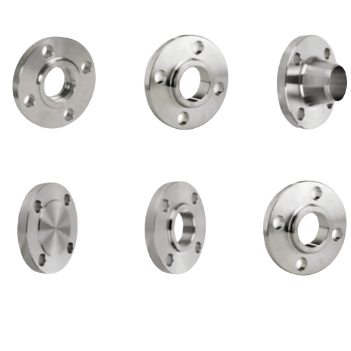
- Types of Pipe Flanges: Complete Selection GuideWN, SO, blind, socket weld, lap joint and more
References & Sources
- LANL Engineering Standards Manual, Process Piping Guide REF-3-R0Los Alamos National Laboratory (U.S. Department of Energy)
- EN 13480 vs. ASME B31 Code Comparison Report (2024) – U.S. Department of Energy (contains ASME B31.3 308.2.4 verbatim)
- B31.3 Process Piping Guide, Revision 2Lawrence Berkeley National Laboratory (U.S. Department of Energy)
- Global Flanges Market Size & Share Report, March 2026Global Market Insights, Inc.
- ASME B31 Piping Updates for Stress Range Factors (Feb 2024) – Paulin Research Group (authoritative commentary on B31.3 2022 Appendix W fatigue updates)