


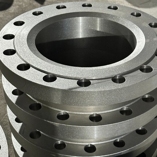
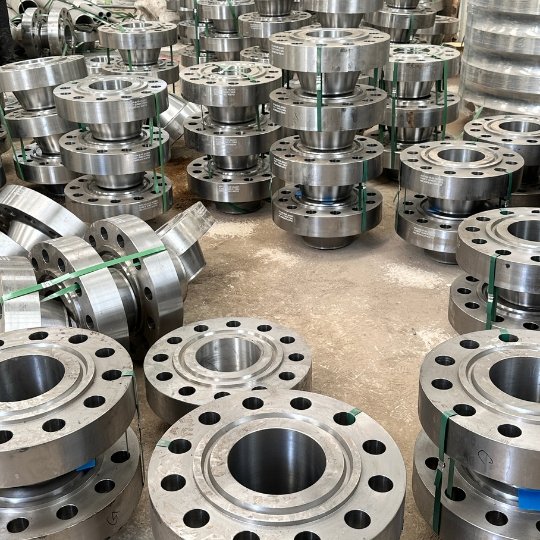
Welded Neck Flange
The Welding Flange Is The Main Component Of A High-Pressure Pipeline System Connection, According To The Different Connection Surfaces Can Be Divided Into RF, FF, RTJ, And SW Types, According To The Material Carbon Steel, Stainless Steel, Alloy Steel, And Duplex Stainless Steel Material.
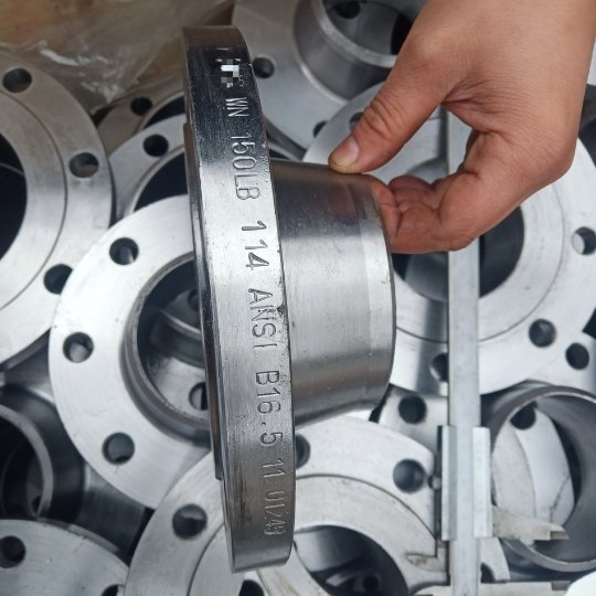
Usually The Implementation Of Standards For ASME B16.5, ASME B16.47, And API 6A Standards, The Pressure Value Of 150lb To 2500lb, 0 ^ 20,000PSI.
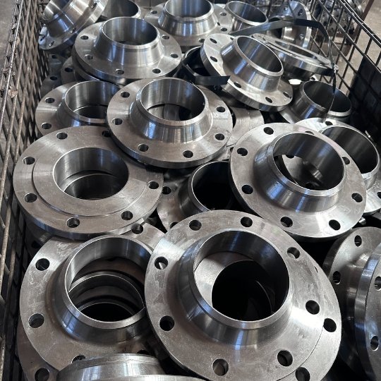
Balingsteel Is A Professional Flange Manufacturer, With A Large Inventory, If You Need It, Please Contact Us!
Recommended Products By Balingsteel
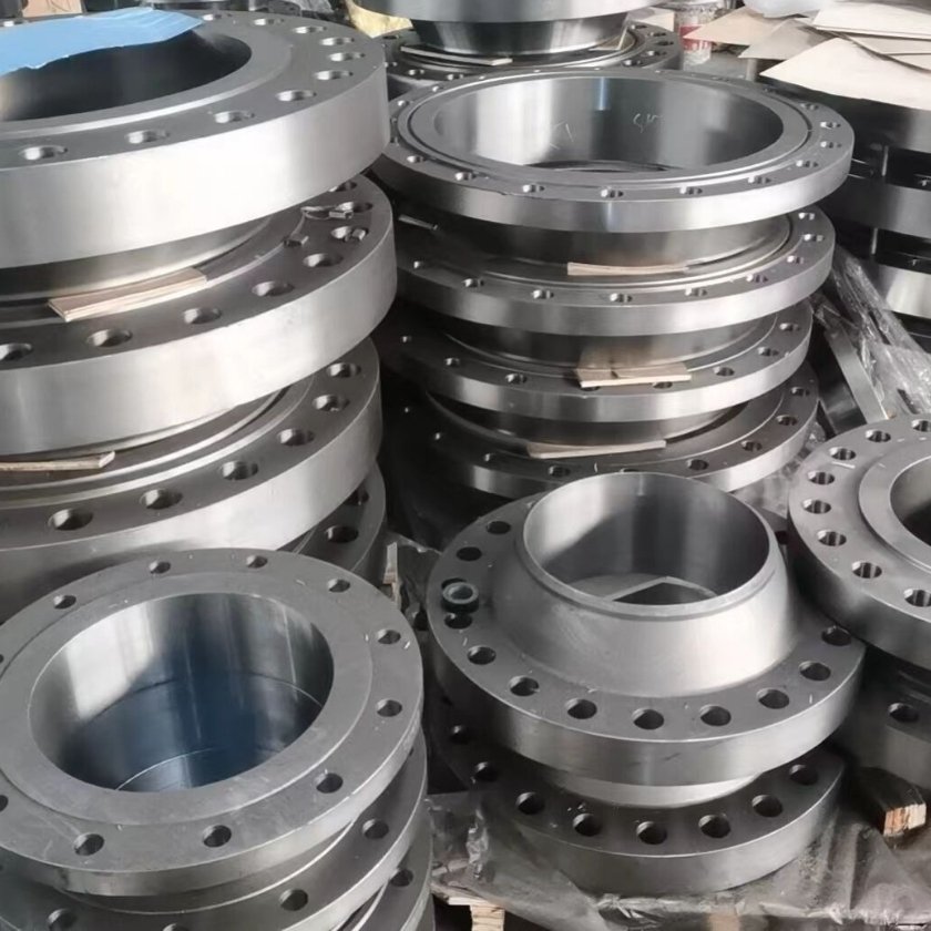
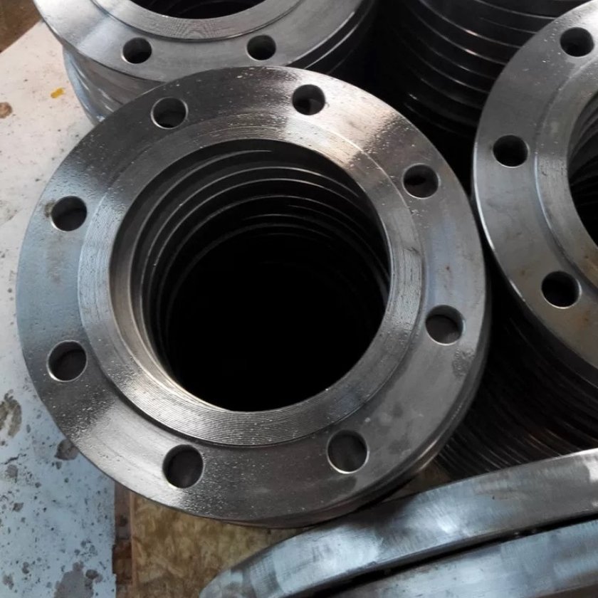
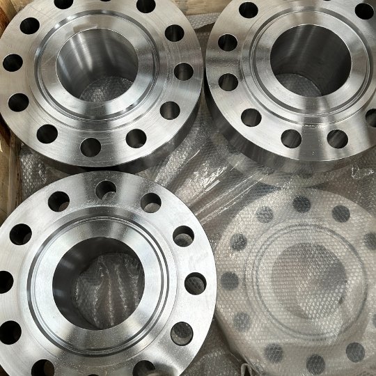
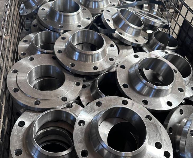
High Quality Welded Neck Flange
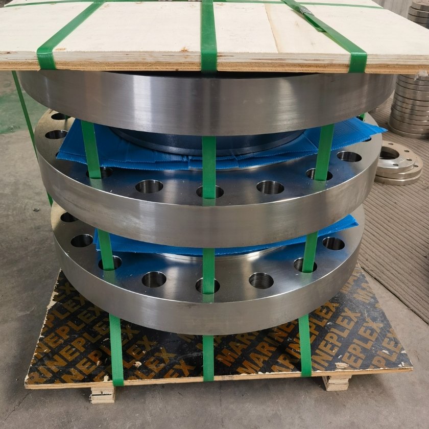
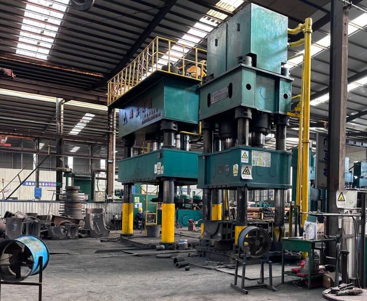
Balingsteel Has More Than 20 Precision Lathes to Process Welded Neck Flange, Forging of Raw Materials, Precision Machining, Heat Treatment, and Tempering, and Customized Packaging Processes, We Have 4 Re-Inspection Processes Above Standard Requirements to Produce Your Flanges.
If You Are Looking for a Reliable Flange Supplier, Balingsteel Will Be Your Good Choice, Please Feel Free to Contact Us for a Quote!
Adequate Stock Welded Neck Flange
Balingsteel Has a Large Stock of Flanges in the Following Standards:
| Flange Size | Pressure Rating | Materials | Standard |
| 1/2″-60″ | Class 150-2500 |
A105, A181, A182, A350 |
ANSI B16.5 MSS SP-44 API 605 |
| 1/2″ – 36″ | Class 150-2500 |
BS 4360 Gr.43A BS970 |
BS4504 BS10 |
We Can Deliver Your Flanges in the Above Standards Within 7 Days, Please Contact Us to Get Your Flanges Now!
Dimensions and Weight
The Following Is the Size Table and Meter Weight Table of Welded Neck Flange, If You Need More Detailed Technical Parameters, Please Feel Free to Contact Us!
- ASME B16.5
- ASME B16.47 Series A
- ASME B16.47 Series B
- EN 1092-1
ASME B16.5 Welded Neck Flange Dimensions and Weight:
Class 150 |
Dimensions in mm | ||||||||||||||
| Nominal Pipe Size |
Outside Diam. of Flange |
Minimum Thickness of Flange |
Minimum Thickness Lap Joint |
O.D.of Raised Face |
Diam. of Hub |
Bore | Length Through Hub | Diam. of Hub at Bevel |
Corner Bore Radius of Lapped Flange and Pipe |
Minimum Thread Length Threaded Flange |
Depth of Socket |
||||
| Welding Neck/ Socket Welding |
Minimum Slip-on/ Socket Welding |
Minimum Lapped |
Welding Neck |
Slip-on/ Threaded/ Socket Welding |
Lapped | ||||||||||
| D | t | t | G | X | B1 | B2 | B3 | T1 | T2 | T3 | A | R | Q | Y | |
| 1/2 | 90 | 9.6 | 11.2 | 34.9 | 30 | 15.8 | 22.2 | 22.9 | 46 | 14 | 16 | 21.3 | 3 | 16 | 10 |
| 3/4 | 100 | 11.2 | 12.7 | 42.9 | 38 | 20.9 | 27.7 | 28.2 | 51 | 14 | 16 | 26.7 | 3 | 16 | 11 |
| 1 | 110 | 12.7 | 14.3 | 50.8 | 49 | 26.6 | 34.5 | 34.9 | 54 | 16 | 17 | 33.4 | 3 | 17 | 13 |
| 1-1/4 | 115 | 14.3 | 15.9 | 63.5 | 59 | 35.1 | 43.2 | 43.7 | 56 | 19 | 21 | 42.2 | 5 | 21 | 14 |
| 1-1/2 | 125 | 15.9 | 17.5 | 73.0 | 65 | 40.9 | 49.5 | 50.0 | 60 | 21 | 22 | 48.3 | 6 | 22 | 16 |
| 2 | 150 | 17.5 | 19.1 | 92.1 | 78 | 52.5 | 61.9 | 62.5 | 62 | 24 | 25 | 60.3 | 8 | 25 | 17 |
| 2-1/2 | 180 | 20.7 | 22.3 | 104.8 | 90 | 62.7 | 74.6 | 75.4 | 68 | 27 | 29 | 73.0 | 8 | 29 | 19 |
| 3 | 190 | 22.3 | 23.9 | 127.0 | 108 | 77.9 | 90.7 | 91.4 | 68 | 29 | 30 | 88.9 | 10 | 30 | 21 |
| 3-1/2 | 215 | 22.3 | 23.9 | 139.7 | 122 | 90.1 | 103.4 | 104.1 | 70 | 30 | 32 | 101.6 | 10 | 32 | – |
| 4 | 230 | 22.3 | 23.9 | 157.2 | 135 | 102.3 | 116.1 | 116.8 | 75 | 32 | 33 | 114.3 | 11 | 33 | – |
| 5 | 255 | 22.3 | 23.9 | 185.7 | 164 | 128.2 | 143.8 | 144.4 | 87 | 35 | 36 | 141.3 | 11 | 36 | – |
| 6 | 280 | 23.9 | 25.4 | 215.9 | 192 | 154.1 | 170.7 | 171.4 | 87 | 38 | 40 | 168.3 | 13 | 40 | – |
| 8 | 345 | 27.0 | 28.6 | 269.9 | 246 | 202.7 | 221.5 | 222.2 | 100 | 43 | 44 | 219.1 | 13 | 44 | – |
| 10 | 405 | 28.6 | 30.2 | 323.8 | 305 | 254.6 | 276.2 | 277.4 | 100 | 48 | 49 | 273.0 | 13 | 49 | – |
| 12 | 485 | 30.2 | 31.8 | 381.0 | 365 | 304.8 | 327.0 | 328.2 | 113 | 54 | 56 | 323.8 | 13 | 56 | – |
| 14 | 535 | 33.4 | 35.0 | 412.8 | 400 | 359.2 | 360.2 | 125 | 56 | 79 | 355.6 | 13 | 57 | – | |
| 16 | 595 | 35.0 | 36.6 | 469.9 | 457 | To be | 410.5 | 411.2 | 125 | 62 | 87 | 406.4 | 13 | 64 | – |
| 18 | 635 | 38.1 | 39.7 | 533.4 | 505 | Specified by the |
461.8 | 462.3 | 138 | 67 | 97 | 457.0 | 13 | 68 | – |
| 20 | 700 | 41.3 | 42.9 | 584.2 | 559 | Purchaser | 513.1 | 514.4 | 143 | 71 | 103 | 508.0 | 13 | 73 | – |
| 24 | 815 | 46.1 | 47.7 | 692.2 | 663 | 616.0 | 616.0 | 151 | 81 | 111 | 610.0 | 13 | 83 | – | |
Class 300 |
Dimensions in mm | |||||||||||||||
| Nominal Pipe Size |
Outside Diam. of Flange |
Minimum Thickness of Flange |
Minimum Thickness Lap Joint |
O.D.of Raised Face |
Diam. of Hub |
Bore | Counter Bore |
Length Through Hub | Diam. of Hub at Bevel |
Corner Bore Radius of Lapped Flange and Pipe |
Minimum Thread Length Threaded Flange |
Depth of Socket |
||||
| Welding Neck/ Socket Welding |
Minimum Slip-on/ Socket Welding |
Minimum Lapped |
Minimum Threaded Flange |
Welding Neck |
Slip-on/ Threaded/ Socket Welding |
Lapped | ||||||||||
| D | t | t | G | X | B1 | B2 | B3 | B | T1 | T2 | T3 | A | R | Q | Y | |
| 1/2 | 95 | 12.7 | 14.3 | 34.9 | 38 | 15.8 | 22.2 | 22.9 | 23.6 | 51 | 21 | 22 | 21.3 | 3 | 16 | 10 |
| 3/4 | 115 | 14.3 | 15.9 | 42.9 | 48 | 20.9 | 27.7 | 28.2 | 29.0 | 56 | 24 | 25 | 26.7 | 3 | 16 | 11 |
| 1 | 125 | 15.9 | 17.5 | 50.8 | 54 | 26.6 | 34.5 | 34.9 | 35.8 | 60 | 25 | 27 | 33.4 | 3 | 18 | 13 |
| 1-1/4 | 135 | 17.5 | 19.1 | 63.5 | 64 | 35.1 | 43.2 | 43.7 | 44.4 | 64 | 25 | 27 | 42.2 | 5 | 21 | 14 |
| 1-1/2 | 155 | 19.1 | 20.7 | 73.0 | 70 | 40.9 | 49.5 | 50.0 | 50.3 | 67 | 29 | 30 | 48.3 | 6 | 23 | 16 |
| 2 | 165 | 20.7 | 22.3 | 92.1 | 84 | 52.5 | 61.9 | 62.5 | 63.5 | 68 | 32 | 33 | 60.3 | 8 | 29 | 17 |
| 2-1/2 | 190 | 23.9 | 25.4 | 104.8 | 100 | 62.7 | 74.6 | 75.4 | 76.2 | 75 | 37 | 38 | 73.0 | 8 | 32 | 19 |
| 3 | 210 | 27.0 | 28.6 | 127.0 | 117 | 77.9 | 90.7 | 91.4 | 92.2 | 78 | 41 | 43 | 88.9 | 10 | 32 | 21 |
| 3-1/2 | 230 | 28.6 | 30.2 | 139.7 | 133 | 90.1 | 103.4 | 104.1 | 104.9 | 79 | 43 | 44 | 101.6 | 10 | 37 | – |
| 4 | 255 | 30.2 | 31.8 | 157.2 | 146 | 102.3 | 116.1 | 116.8 | 117.6 | 84 | 46 | 48 | 114.3 | 11 | 37 | – |
| 5 | 280 | 33.4 | 35.0 | 185.7 | 178 | 128.2 | 143.8 | 144.4 | 144.4 | 97 | 49 | 51 | 141.3 | 11 | 43 | – |
| 6 | 320 | 35.0 | 36.6 | 215.9 | 206 | 154.1 | 170.7 | 171.4 | 171.4 | 97 | 51 | 52 | 168.3 | 13 | 47 | – |
| 8 | 380 | 39.7 | 41.3 | 269.9 | 260 | 202.7 | 221.5 | 222.2 | 222.2 | 110 | 60 | 62 | 219.1 | 13 | 51 | – |
| 10 | 445 | 46.1 | 47.7 | 323.8 | 321 | 254.6 | 276.2 | 277.4 | 276.2 | 116 | 65 | 95 | 273.0 | 13 | 56 | – |
| 12 | 520 | 49.3 | 50.8 | 381.0 | 375 | 304.8 | 327.0 | 328.2 | 328.6 | 129 | 71 | 102 | 323.8 | 13 | 61 | – |
| 14 | 585 | 52.4 | 54.0 | 412.8 | 425 | 359.2 | 360.2 | 360.4 | 141 | 75 | 111 | 355.6 | 13 | 64 | – | |
| 16 | 650 | 55.6 | 57.2 | 469.9 | 483 | To be | 410.5 | 411.2 | 411.2 | 144 | 81 | 121 | 406.4 | 13 | 69 | – |
| 18 | 710 | 58.8 | 60.4 | 533.4 | 533 | specified by the |
461.8 | 462.3 | 462.0 | 157 | 87 | 130 | 457.0 | 13 | 70 | – |
| 20 | 775 | 62.0 | 63.5 | 584.2 | 587 | Purchaser | 513.1 | 514.4 | 512.8 | 160 | 94 | 140 | 508.0 | 13 | 74 | – |
| 24 | 915 | 68.3 | 69.9 | 692.2 | 702 | 616.0 | 616.0 | 614.4 | 167 | 105 | 152 | 616.0 | 13 | 83 | – | |
Class 600 |
Dimensions in mm | ||||||||||||||
| Nominal Pipe Size |
Outside Diam. of Flange |
Minimum Thickness of Flange |
O.D.of Raised Face |
Diam. of Hub |
Bore | Counter Bore |
Length Through Hub | Diam. of Hub at Bevel |
Corner Bore Radius of Lapped Flange and Pipe |
Minimum Thread Length Threaded Flange |
Depth of Socket |
||||
| Welding Neck/ Socket Welding |
Minimum Slip-on/ Socket Welding |
Minimum Lapped |
Minimum Threaded Flange |
Welding Neck |
Slip-on/ Threaded/ Socket Welding |
Lapped | |||||||||
| D | t | G | X | B1 | B2 | B3 | B | T1 | T2 | T3 | A | R | Q | Y | |
| 1/2 | 95 | 14.3 | 34.9 | 38 | 22.2 | 22.9 | 23.6 | 52 | 22 | 22 | 21.3 | 3 | 16 | 10 | |
| 3/4 | 115 | 15.9 | 42.9 | 48 | 27.7 | 28.2 | 29.0 | 57 | 25 | 25 | 26.7 | 3 | 16 | 11 | |
| 1 | 125 | 17.5 | 50.8 | 54 | 34.5 | 34.9 | 35.8 | 62 | 27 | 27 | 33.4 | 3 | 18 | 13 | |
| 1-1/4 | 135 | 20.7 | 63.5 | 64 | 43.2 | 43.7 | 44.4 | 67 | 29 | 29 | 42.2 | 5 | 21 | 14 | |
| 1-1/2 | 155 | 22.3 | 73.0 | 70 | 49.5 | 50.0 | 50.6 | 70 | 32 | 32 | 48.3 | 6 | 23 | 16 | |
| 2 | 165 | 25.4 | 92.1 | 84 | 61.9 | 62.5 | 63.5 | 73 | 37 | 37 | 60.3 | 8 | 29 | 17 | |
| 2-1/2 | 190 | 28.6 | 104.8 | 100 | 74.6 | 75.4 | 76.2 | 79 | 41 | 41 | 73.0 | 8 | 32 | 19 | |
| 3 | 210 | 31.8 | 127.0 | 117 | 90.7 | 91.4 | 92.2 | 83 | 46 | 46 | 88.9 | 10 | 35 | 21 | |
| 3-1/2 | 230 | 35.0 | 139.7 | 133 | 103.4 | 104.1 | 104.9 | 86 | 49 | 49 | 101.6 | 10 | 40 | – | |
| 4 | 275 | 38.1 | 157.2 | 152 | To be specified |
116.1 | 116.8 | 117.6 | 102 | 54 | 54 | 114.3 | 11 | 42 | – |
| 5 | 330 | 44.5 | 185.7 | 189 | by the Purchaser. |
143.8 | 144.4 | 144.4 | 114 | 60 | 60 | 141.3 | 11 | 48 | – |
| 6 | 355 | 47.7 | 215.9 | 222 | 170.7 | 171.4 | 171.4 | 117 | 67 | 67 | 168.3 | 13 | 51 | – | |
| 8 | 420 | 55.6 | 269.9 | 273 | 221.5 | 222.2 | 222.2 | 133 | 76 | 76 | 219.1 | 13 | 58 | – | |
| 10 | 510 | 63.5 | 323.8 | 343 | 276.2 | 277.4 | 276.2 | 152 | 86 | 111 | 273.0 | 13 | 66 | – | |
| 12 | 560 | 66.7 | 381.0 | 400 | 327.0 | 328.2 | 328.6 | 156 | 92 | 117 | 323.8 | 13 | 70 | – | |
| 14 | 605 | 69.9 | 412.8 | 432 | 359.2 | 360.2 | 360.4 | 165 | 94 | 127 | 355.6 | 13 | 74 | – | |
| 16 | 685 | 76.2 | 469.9 | 495 | 410.5 | 411.2 | 411.2 | 178 | 106 | 140 | 406.4 | 13 | 78 | – | |
| 18 | 745 | 82.6 | 533.4 | 546 | 461.8 | 462.3 | 462.0 | 184 | 117 | 152 | 457.0 | 13 | 80 | – | |
| 20 | 815 | 88.9 | 584.2 | 610 | 513.1 | 514.4 | 512.8 | 190 | 127 | 165 | 508.0 | 13 | 83 | – | |
| 24 | 940 | 101.6 | 692.2 | 718 | 616.0 | 616.0 | 614.4 | 203 | 140 | 184 | 610.0 | 13 | 93 | – | |
Class 900 |
Dimensions in mm | |||||||||||||
| Nominal Pipe Size |
Outside Diam. of Flange |
Minimum Thickness of Flange |
O.D.of Raised Face |
Diam. of Hub |
Bore | Counter Bore |
Length Through Hub | Diam. of Hub at Bevel |
Corner Bore Radius of Lapped Flange and Pipe |
Minimum Thread Length Threaded Flange |
||||
| Welding Neck |
Minimum Slip-on |
Minimum Lapped |
Minimum Threaded Flange |
Welding Neck |
Slip-on/ Threaded |
Lapped | ||||||||
| D | t | G | X | B1 | B2 | B3 | B | T1 | T2 | T3 | A | R | Q | |
| 1/2 | 120 | 22.3 | 34.9 | 38 | 22.2 | 22.9 | 23.6 | 60 | 32 | 32 | 21.3 | 3 | 23 | |
| 3/4 | 130 | 25.4 | 42.9 | 44 | To be specified by the Purchaser. |
27.7 | 28.2 | 29.0 | 70 | 35 | 35 26.7 | 3 | 26 | |
| 1 | 150 | 28.6 | 50.8 | 52 | 34.5 | 34.9 | 35.8 | 73 | 41 | 41 | 33.4 | 3 | 29 | |
| 1-1/4 | 160 | 28.6 | 63.5 | 64 | 43.2 | 43.7 | 44.4 | 73 | 41 | 41 | 42.2 | 5 | 31 | |
| 1-1/2 | 180 | 31.8 | 73.0 | 70 | 49.5 | 50.0 | 50.6 | 83 | 44 | 44 | 48.3 | 6 | 32 | |
| 2 | 215 | 38.1 | 92.1 | 105 | 61.9 | 62.5 | 63.5 | 102 | 57 | 57 60.3 | 8 | 39 | ||
| 2-1/2 | 245 | 41.3 | 104.8 | 124 | 74.6 | 75.4 | 76.2 | 105 | 64 | 64 | 73.0 | 8 | 48 | |
| 3 | 240 | 38.1 | 127.0 | 127 | 90.7 | 91.4 | 92.2 | 102 | 54 | 54 | 88.9 | 10 | 42 | |
| 4 | 290 | 44.5 | 157.2 | 159 | 116.1 | 116.8 | 117.6 | 114 | 70 | 70 | 114.3 | 11 | 48 | |
| 5 | 350 | 50.8 | 185.7 | 190 | 143.8 | 144.4 | 144.4 | 127 | 79 | 79 | 141.3 | 11 | 54 | |
| 6 | 380 | 55.6 | 215.9 | 235 | 170.7 | 171.4 | 171.4 | 140 | 86 | 86 | 168.3 | 13 | 58 | |
| 8 | 470 | 63.5 | 269.9 | 298 | 221.5 | 222.2 | 222.2 | 162 | 102 | 114 | 219.1 | 13 | 64 | |
| 10 | 545 | 69.9 | 323.8 | 368 | 276.2 | 277.4 | 276.2 | 184 | 108 | 127 | 273.0 | 13 | 72 | |
| 12 | 610 | 79.4 | 381.0 | 419 | 327.0 | 328.2 | 328.6 | 200 | 117 | 143 | 323.8 | 13 | 77 | |
| 14 | 640 | 85.8 | 412.8 | 451 | 359.2 | 360.2 | 360.4 | 213 | 130 | 156 | 355.6 | 13 | 83 | |
| 16 | 705 | 88.9 | 469.9 | 508 | 410.5 | 411.2 | 411.2 | 216 | 133 | 165 | 406.4 | 13 | 86 | |
| 18 | 785 | 101.6 | 533.4 | 565 | 461.8 | 462.3 | 462.0 | 229 | 152 | 190 | 457.0 | 13 | 89 | |
| 20 | 855 | 108.0 | 584.2 | 622 | 513.1 | 514.4 | 512.8 | 248 | 159 | 210 | 508.0 | 13 | 93 | |
| 24 | 1040 | 139.7 | 692.2 | 749 | 616.0 | 616.0 | 614.4 | 292 | 203 | 267 | 610.0 | 13 | 102 | |
Class 1500 |
Dimensions in mm | ||||||||||||||
| Nominal Pipe Size |
Outside Diam. of Flange |
Minimum Thickness of Flange |
O.D.of Raised Face |
Diam. of Hub |
Bore | Counter Bore |
Length Through Hub | Diam. of Hub at Bevel |
Corner Bore Radius of Fillet of Lapped |
Minimum Thread Length Threaded Flange |
Depth of Socket |
||||
| Welding Neck/ Socket Welding |
Minimum Slip-on/ Socket Welding |
Minimum Lapped |
Minimum Threaded Flange |
Welding Neck |
Slip-on/ Threaded/ Socket Welding |
Lapped | |||||||||
| D | t | G | X | B1 | B2 | B3 | B | T1 | T2 | T3 | A | R | Q | Y | |
| 1/2 | 120 | 22.3 | 34.9 | 38 | 22.2 | 22.9 | 23.6 | 60 | 32 | 32 | 21.3 | 3 | 23 | 10 | |
| 3/4 | 130 | 25.4 | 42.9 | 44 | 27.7 | 28.2 | 29.0 | 70 | 35 | 35 | 26.7 | 3 | 26 | 11 | |
| 1 | 150 | 28.6 | 50.8 | 52 | 34.5 | 34.9 | 35.8 | 73 | 41 | 41 | 33.4 | 3 | 29 | 13 | |
| 1-1/4 | 160 | 28.6 | 63.5 | 64 | 43.2 | 43.7 | 44.4 | 73 | 41 | 41 | 42.2 | 5 | 31 | 14 | |
| 1-1/2 | 180 | 31.8 | 73.0 | 70 | 49.5 | 50.0 | 50.6 | 83 | 44 | 44 | 48.3 | 6 | 32 | 16 | |
| 2 | 215 | 38.1 | 92.1 | 105 | 61.9 | 62.5 | 63.5 | 102 | 57 | 57 | 60.3 | 8 | 39 | 17 | |
| 2-1/2 | 245 | 41.3 | 104.8 | 124 | 74.6 | 75.4 | 76.2 | 105 | 64 | 64 | 73.0 | 8 | 48 | 19 | |
| 3 | 265 | 47.7 | 127.0 | 133 | – | 91.4 | – | 117 | – | 73 | 88.9 | 10 | – | – | |
| 4 | 310 | 54.0 | 157.2 | 162 | To be | – | 116.8 | – | 124 | – | 90 | 114.3 | 11 | – | – |
| 5 | 375 | 73.1 | 185.7 | 197 | specified by the |
– | 144.4 | – | 156 | – | 105 | 141.3 | 11 | – | – |
| 6 | 395 | 82.6 | 215.9 | 229 | Purchaser. | – | 171.4 | – | 171 | – | 119 | 168.3 | 13 | – | – |
| 8 | 485 | 92.1 | 269.9 | 292 | – | 222.2 | – | 213 | – | 143 | 219.1 | 13 | – | – | |
| 10 | 585 | 108.0 | 323.8 | 368 | – | 277.4 | – | 254 | – | 178 | 273.0 | 13 | – | – | |
| 12 | 675 | 123.9 | 381.0 | 451 | – | 328.2 | – | 283 | – | 219 | 323.8 | 13 | – | – | |
| 14 | 750 | 133.4 | 412.8 | 495 | – | 360.2 | – | 298 | – | 241 | 355.6 | 13 | – | – | |
| 16 | 825 | 146.1 | 469.9 | 552 | – | 411.2 | – | 311 | – | 260 | 406.4 | 13 | – | – | |
| 18 | 915 | 162.0 | 533.4 | 597 | – | 462.3 | – | 327 | – | 276 | 457.0 | 13 | – | – | |
| 20 | 985 | 177.8 | 584.2 | 641 | – | 514.4 | – | 356 | – | 292 | 508.0 | 13 | – | – | |
| 24 | 1170 | 203.2 | 692.2 | 762 | – | 616.0 | – | 406 | – | 330 | 610.0 | 13 | – | – | |
If You Want More Details About Welded Neck Flange, Please Feel Free to Contact Us!
ASME B16.47 Series A Welded Neck Flange Dimensions and Weight:
Class 150 Series A |
Dimensions in mm | |||||||||||
| Nominal Pipe Size |
O.D.of Flange,O |
Minimum Thickness of Flange,tf [Note(1)] |
Length Through Hub,Y |
Diam.of Hub,X [Note(2)] |
Hub Diam. Top,A |
Raised Face Diam.,R |
Drilling | Diam. of Bolt |
Minimum Fillet Radius,r1 |
|||
| Diam. of Bolt Circle |
No.of Bolt Holes |
Diam. of Bolt Hole |
||||||||||
| WNF | Blind | |||||||||||
| 26 | 870 | 66.7 | 66.7 | 119 | 676 | 660.4 | 749 | 806.4 | 24 | 1-3/8 | 1-1/4 | 10 |
| 28 | 925 | 69.9 | 69.9 | 124 | 727 | 711.2 | 800 | 863.6 | 28 | 1-3/8 | 1-1/4 | 11 |
| 30 | 985 | 73.1 | 73.1 | 135 | 781 | 762.0 | 857 | 914.4 | 28 | 1-3/8 | 1-1/4 | 11 |
| 32 | 1060 | 79.4 | 79.4 | 143 | 832 | 812.8 | 914 | 977.9 | 28 | 1-5/8 | 1-1/2 | 11 |
| 34 | 1110 | 81.0 | 81.0 | 148 | 883 | 863.6 | 965 | 1028.7 | 32 | 1-5/8 | 1-1/2 | 13 |
| 36 | 1170 | 88.9 | 88.9 | 156 | 933 | 914.4 | 1022 | 1085.8 | 32 | 1-5/8 | 1-1/2 | 13 |
| 38 | 1240 | 85.8 | 85.8 | 156 | 991 | 965.2 | 1073 | 1149.4 | 32 | 1-5/8 | 1-1/2 | 13 |
| 40 | 1290 | 88.9 | 88.9 | 162 | 1041 | 1016.0 | 1124 | 1200.2 | 36 | 1-5/8 | 1-1/2 | 13 |
| 42 | 1345 | 95.3 | 95.3 | 170 | 1092 | 1066.8 | 1194 | 1257.3 | 36 | 1-5/8 | 1-1/2 | 13 |
| 44 | 1405 | 100.1 | 100.1 | 176 | 1143 | 1117.6 | 1245 | 1314.4 | 40 | 1-5/8 | 1-1/2 | 13 |
| 46 | 1455 | 101.6 | 101.6 | 184 | 1197 | 1168.4 | 1295 | 1365.2 | 40 | 1-5/8 | 1-1/2 | 13 |
| 48 | 1510 | 106.4 | 106.4 | 191 | 1248 | 1219.2 | 1359 | 1422.4 | 44 | 1-5/8 | 1-1/2 | 13 |
| 50 | 1570 | 109.6 | 109.6 | 202 | 1302 | 1270.0 | 1410 | 1479.6 | 44 | 1-7/8 | 1-3/4 | 13 |
| 52 | 1625 | 114.3 | 114.3 | 208 | 1353 | 1320.8 | 1461 | 1536.7 | 44 | 1-7/8 | 1-3/4 | 13 |
| 54 | 1685 | 119.1 | 119.1 | 214 | 1403 | 1371.6 | 1511 | 1593.8 | 44 | 1-7/8 | 1-3/4 | 13 |
| 56 | 1745 | 122.3 | 122.3 | 227 | 1457 | 1422.4 | 1575 | 1651.0 | 48 | 1-7/8 | 1-3/4 | 13 |
| 58 | 1805 | 127.0 | 127.0 | 233 | 1508 | 1473.2 | 1626 | 1708.2 | 48 | 1-7/8 | 1-3/4 | 13 |
| 60 | 1855 | 130.2 | 130.2 | 238 | 1559 | 1524.0 | 1676 | 1759.0 | 52 | 1-7/8 | 1-3/4 | 13 |
Class 300 Series A |
Dimensions in mm | |||||||||||
| Nominal Pipe Size |
O.D.of Flange,O |
Minimum Thickness of Flange,tf [Note(1)] |
Length Through Hub,Y |
Diam.of Hub,X [Note(2)] |
Hub Diam. Top,A |
Raised Face Diam.,R |
Drilling | Diam. of Bolt |
Minimum Fillet Radius,r1 |
|||
| Diam. of Bolt Circle |
No.of Bolt Holes |
Diam. of Bolt Hole |
||||||||||
| WNF | Blind | |||||||||||
| 26 | 970 | 77.8 | 82.6 | 183 | 721 | 660.4 | 749 | 876.3 | 28 | 1-3/4 | 1-5/8 | 10 |
| 28 | 1035 | 84.2 | 88.9 | 195 | 775 | 711.2 | 800 | 939.8 | 28 | 1-3/4 | 1-5/8 | 11 |
| 30 | 1090 | 90.5 | 93.7 | 208 | 827 | 762.0 | 857 | 997.0 | 28 | 1-7/8 | 1-3/4 | 11 |
| 32 | 1150 | 96.9 | 98.5 | 221 | 881 | 812.8 | 914 | 1054.1 | 28 | 2 | 1-7/8 | 11 |
| 34 | 1205 | 100.1 | 103.2 | 230 | 937 | 863.6 | 965 | 1104.9 | 28 | 2 | 1-7/8 | 13 |
| 36 | 1270 | 103.2 | 109.6 | 240 | 991 | 914.4 | 1022 | 1168.4 | 32 | 2-1/8 | 2 | 13 |
| 38 | 1170 | 106.4 | 106.4 | 179 | 994 | 965.2 | 1029 | 1092.2 | 32 | 1-5/8 | 1-1/2 | 13 |
| 40 | 1240 | 112.8 | 112.8 | 192 | 1048 | 1016.0 | 1086 | 1155.7 | 32 | 1-3/4 | 1-5/8 | 13 |
| 42 | 1290 | 117.5 | 117.5 | 198 | 1099 | 1066.8 | 1137 | 1206.5 | 32 | 1-3/4 | 1-5/8 | 13 |
| 44 | 1355 | 122.3 | 122.3 | 205 | 1149 | 1117.6 | 1194 | 1263.6 | 32 | 1-7/8 | 1-3/4 | 13 |
| 46 | 1415 | 127.0 | 127.0 | 214 | 1203 | 1168.4 | 1245 | 1320.8 | 28 | 2 | 1-7/8 | 13 |
| 48 | 1465 | 131.8 | 131.8 | 222 | 1254 | 1219.2 | 1302 | 1371.6 | 32 | 2 | 1-7/8 | 13 |
| 50 | 1530 | 138.2 | 138.2 | 230 | 1305 | 1270.0 | 1359 | 1428.8 | 32 | 2-1/8 | 2 | 13 |
| 52 | 1580 | 142.9 | 142.9 | 237 | 1356 | 1320.8 | 1410 | 1479.6 | 32 | 2-1/8 | 2 | 13 |
| 54 | 1660 | 150.9 | 150.9 | 251 | 1410 | 1371.6 | 1467 | 1549.4 | 28 | 2-3/8 | 2-1/4 | 13 |
| 56 | 1710 | 152.4 | 152.4 | 259 | 1464 | 1422.4 | 1518 | 1600.2 | 28 | 2-3/8 | 2-1/4 | 13 |
| 58 | 1760 | 157.2 | 157.2 | 265 | 1514 | 1473.2 | 1575 | 1651.0 | 32 | 2-3/8 | 2-1/4 | 13 |
| 60 | 1810 | 162.0 | 162.0 | 271 | 1565 | 1524.0 | 1626 | 1701.8 | 32 | 2-3/8 | 2-1/4 | 13 |
Class 400 Series A |
Dimensions in mm | |||||||||||
| Nominal Pipe Size |
Minimum Thickness of Flange, [Note(1)] |
Length Through Hub,Y |
Diam.of Hub,X [Note(2)] |
Hub Diam. Top,A |
Raised Face Diam.,R |
Drilling | Diam. of Bolt |
Minimum Fillet Radius,r1 |
||||
| O.D.of Flange,O |
Diam. of Bolt Circle |
No.of Bolt Holes |
Diam. of Bolt Hole |
|||||||||
| WNF | Blind | |||||||||||
| 26 | 970 | 88.9 | 98.5 | 194 | 727 | 660.4 | 749 | 876.3 | 28 | 1-7/8 | 1-3/4 | 11 |
| 28 | 1035 | 95.3 | 104.8 | 206 | 783 | 711.2 | 800 | 939.8 | 28 | 2 | 1-7/8 | 13 |
| 30 | 1090 | 101.6 | 111.2 | 219 | 837 | 762.0 | 857 | 997.0 | 28 | 2-1/8 | 2 | 13 |
| 32 | 1150 | 108.0 | 115.9 | 232 | 889 | 812.8 | 914 | 1054.1 | 28 | 2-1/8 | 2 | 13 |
| 34 | 1205 | 111.2 | 122.3 | 241 | 945 | 863.6 | 965 | 1104.9 | 28 | 2-1/8 | 2 | 14 |
| 36 | 1270 | 114.3 | 128.6 | 251 | 1000 | 914.4 | 1022 | 1168.4 | 32 | 2-1/8 | 2 | 14 |
| 38 | 1205 | 123.9 | 123.9 | 206 | 1003 | 965.2 | 1035 | 1117.6 | 32 | 1-7/8 | 1-3/4 | 14 |
| 40 | 1270 | 130.2 | 130.2 | 216 | 1054 | 1016.0 | 1092 | 1174.8 | 32 | 2 | 1-7/8 | 14 |
| 42 | 1320 | 133.4 | 133.4 | 224 | 1108 | 1066.8 | 1143 | 1225.6 | 32 | 2 | 1-7/8 | 14 |
| 44 | 1385 | 139.7 | 139.7 | 233 | 1159 | 1117.6 | 1200 | 1282.7 | 32 | 2-1/8 | 2 | 14 |
| 46 | 1440 | 146.1 | 146.1 | 244 | 1213 | 1168.4 | 1257 | 1339.8 | 36 | 2-1/8 | 2 | 14 |
| 48 | 1510 | 152.4 | 152.4 | 257 | 1267 | 1219.2 | 1308 | 1403.4 | 28 | 2-3/8 | 2-1/4 | 14 |
| 50 | 1570 | 157.2 | 158.8 | 268 | 1321 | 1270.0 | 1362 | 1460.5 | 32 | 2-3/8 | 2-1/4 | 14 |
| 52 | 1620 | 162.0 | 163.6 | 276 | 1372 | 1320.8 | 1413 | 1511.3 | 32 | 2-3/8 | 2-1/4 | 14 |
| 54 | 1700 | 169.9 | 171.5 | 289 | 1426 | 1371.6 | 1470 | 1581.2 | 28 | 2-5/8 | 2-1/2 | 14 |
| 56 | 1755 | 174.7 | 176.3 | 298 | 1480 | 1422.4 | 1527 | 1632.0 | 32 | 2-5/8 | 2-1/2 | 14 |
| 58 | 1805 | 177.8 | 181.0 | 306 | 1530 | 1473.2 | 1578 | 1682.8 | 32 | 2-5/8 | 2-1/2 | 14 |
| 60 | 1885 | 185.8 | 189.0 | 319 | 1584 | 1524.0 | 1635 | 1752.6 | 32 | 2-7/8 | 2-3/4 | 14 |
Class 600 Series A |
Dimensions in mm | |||||||||||
| Nominal Pipe Size |
O.D.of Flange,O |
Minimum Thickness of Flange,tf [Note(1)] |
Length Through Hub,Y |
Diam.of Hub,X [Note(2)] |
Hub Diam. Top,A |
Raised Face Diam.,R |
Drilling | Diam. of Bolt |
Minimum Fillet Radius,r1 |
|||
| Diam. of Bolt Circle |
No.of Bolt Holes |
Diam. of Bolt Hole |
||||||||||
| WNF | Blind | |||||||||||
| 26 | 1015 | 108.0 | 125.5 | 222 | 748 | 660.4 | 749 | 914.4 | 28 | 2 | 1-7/8 | 13 |
| 28 | 1075 | 111.2 | 131.8 | 235 | 803 | 711.2 | 800 | 965.2 | 28 | 2-1/8 | 2 | 13 |
| 30 | 1130 | 114.3 | 139.7 | 248 | 862 | 762.0 | 857 | 1022.4 | 28 | 2-1/8 | 2 | 13 |
| 32 | 1195 | 117.5 | 147.7 | 260 | 918 | 812.8 | 914 | 1079.5 | 28 | 2-3/8 | 2-1/4 | 13 |
| 34 | 1245 | 120.7 | 154.0 | 270 | 973 | 863.6 | 965 | 1130.3 | 28 | 2-3/8 | 2-1/4 | 14 |
| 36 | 1315 | 123.9 | 162.0 | 283 | 1032 | 914.4 | 1022 | 1193.8 | 28 | 2-5/8 | 2-1/2 | 14 |
| 38 | 1270 | 152.4 | 155.0 | 254 | 1022 | 965.2 | 1054 | 1162.0 | 28 | 2-3/8 | 2-1/4 | 14 |
| 40 | 1320 | 158.8 | 162.0 | 264 | 1073 | 1016.0 | 1111 | 1212.8 | 32 | 2-3/8 | 2-1/4 | 14 |
| 42 | 1405 | 168.3 | 171.5 | 279 | 1127 | 1066.8 | 1168 | 1282.7 | 28 | 2-5/8 | 2-1/2 | 14 |
| 44 | 1455 | 173.1 | 177.8 | 289 | 1181 | 1117.6 | 1226 | 1333.5 | 32 | 2-5/8 | 2-1/2 | 14 |
| 46 | 1510 | 179.4 | 185.8 | 300 | 1235 | 1168.4 | 1276 | 1390.6 | 32 | 2-5/8 | 2-1/2 | 14 |
| 48 | 1595 | 189.0 | 195.3 | 316 | 1289 | 1219.2 | 1334 | 1460.5 | 32 | 2-7/8 | 2-3/4 | 14 |
| 50 | 1670 | 196.9 | 203.2 | 329 | 1343 | 1270.0 | 1384 | 1524.0 | 28 | 3-1/8 | 3 | 14 |
| 52 | 1720 | 203.2 | 209.6 | 337 | 1394 | 1320.8 | 1435 | 1574.8 | 32 | 3-1/8 | 3 | 14 |
| 54 | 1780 | 209.6 | 217.5 | 349 | 1448 | 1371.6 | 1492 | 1632.0 | 32 | 3-1/8 | 3 | 14 |
| 56 | 1855 | 217.5 | 225.5 | 362 | 1502 | 1422.4 | 1543 | 1695.4 | 32 | 3-3/8 | 3-1/4 | 16 |
| 58 | 1905 | 222.3 | 231.8 | 370 | 1553 | 1473.2 | 1600 | 1746.2 | 32 | 3-3/8 | 3-1/4 | 16 |
| 60 | 1995 | 233.4 | 242.9 | 389 | 1610 | 1524.0 | 1657 | 1822.4 | 28 | 3-5/8 | 3-1/2 | 17 |
Class 900 Series A |
Dimensions in mm | |||||||||||
| Nominal Pipe Size |
O.D.of Flange,O |
Minimum Thickness of Flange,tf [Note(1)] |
Length Through Hub,Y |
Diam.of Hub,X [Note(2)] |
Hub Diam. Top,A |
Raised Face Diam.,R |
Drilling | Diam. of Bolt |
Minimum Fillet Radius,r1 |
|||
| Diam. of Bolt Circle |
No.of Bolt Holes |
Diam. of Bolt Hole |
||||||||||
| WNF | Blind | |||||||||||
| 26 | 1085 | 139.7 | 160.4 | 286 | 775 | 660.4 | 749 | 952.5 | 20 | 2-7/8 | 2-3/4 | 11 |
| 28 | 1170 | 142.9 | 171.5 | 298 | 832 | 711.2 | 800 | 1022.4 | 20 | 3-1/8 | 3 | 13 |
| 30 | 1230 | 149.3 | 182.6 | 311 | 889 | 762.0 | 857 | 1085.8 | 20 | 3-1/8 | 3 | 13 |
| 32 | 1315 | 158.8 | 193.7 | 330 | 946 | 812.8 | 914 | 1155.7 | 20 | 3-3/8 | 3-1/4 | 13 |
| 34 | 1395 | 165.1 | 204.8 | 349 | 1006 | 863.6 | 965 | 1225.6 | 20 | 3-5/8 | 3-1/2 | 14 |
| 36 | 1460 | 171.5 | 214.4 | 362 | 1064 | 914.4 | 1022 | 1289.0 | 20 | 3-5/8 | 3-1/2 | 14 |
| 38 | 1460 | 190.5 | 215.9 | 352 | 1073 | 965.2 | 1099 | 1289.0 | 20 | 3-5/8 | 3-1/2 | 19 |
| 40 | 1510 | 196.9 | 223.9 | 364 | 1127 | 1016.0 | 1162 | 1339.8 | 24 | 3-5/8 | 3-1/2 | 21 |
| 42 | 1560 | 206.4 | 231.8 | 371 | 1176 | 1066.8 | 1213 | 1390.6 | 24 | 3-5/8 | 3-1/2 | 21 |
| 44 | 1650 | 214.4 | 242.9 | 391 | 1235 | 1117.6 | 1270 | 1463.7 | 24 | 3-7/8 | 3-3/4 | 22 |
| 46 | 1735 | 225.5 | 255.6 | 411 | 1292 | 1168.4 | 1334 | 1536.7 | 24 | 4-1/8 | 4 | 22 |
| 48 | 1785 | 233.4 | 263.6 | 419 | 1343 | 1219.2 | 1384 | 1587.5 | 24 | 4-1/8 | 4 | 24 |
| 50 | … | … | … | … | … | … | … | … | … | … | … | … |
| 52 | … | … | … | … | … | … | … | … | … | … | … | … |
| 54 | … | … | … | … | … | … | … | … | … | … | … | … |
| 56 | … | … | … | … | … | … | … | … | … | … | … | … |
| 58 | … | … | … | … | … | … | … | … | … | … | … | … |
| 60 | … | … | … | … | … | … | … | … | … | … | … | … |
If You Want More Details About Welded Neck Flange, Please Feel Free to Contact Us!
ASME B16.47 Series B Welded Neck Flange Dimensions and Weight:

Class 75 Series B |
Dimensions in mm | |||||||||||
| Nominal Pipe Size |
O.D.of Flange,O |
Minimum Thickness of Flange,tf [Note(1)] |
Length Through Hub,Y |
Diam.of Hub,X [Note(2)] |
Hub Diam. Top,A |
Raised Face Diam.,R |
Drilling | Diam. of Bolt |
Minimum Fillet Radius,r1 |
|||
| Diam. of Bolt Circle |
No.of Bolt Holes |
Diam. of Bolt Hole |
||||||||||
| WNF | Blind | |||||||||||
| 26 | 760 | 31.9 | 31.9 | 57 | 676 | 661.9 | 705 | 723.9 | 36 | 3⁄4 | 5⁄8 | 8 |
| 28 | 815 | 31.9 | 31.9 | 60 | 727 | 712.7 | 756 | 774.7 | 40 | 3⁄4 | 5⁄8 | 8 |
| 30 | 865 | 31.9 | 31.9 | 64 | 778 | 763.5 | 806 | 825.5 | 44 | 3⁄4 | 5⁄8 | 8 |
| 32 | 915 | 33.5 | 35.0 | 68 | 829 | 814.3 | 857 | 876.3 | 48 | 3⁄4 | 5⁄8 | 8 |
| 34 | 965 | 33.5 | 36.6 | 72 | 879 | 865.1 | 908 | 927.1 | 52 | 3⁄4 | 5⁄8 | 8 |
| 36 | 1035 | 35.0 | 40.9 | 84 | 935 | 915.9 | 965 | 992.2 | 40 | 7⁄8 | 3⁄4 | 10 |
| 38 | 1085 | 36.6 | 43.0 | 87 | 986 | 966.7 | 1016 | 1043 | 40 | 7⁄8 | 3⁄4 | 10 |
| 40 | 1135 | 36.6 | 43.0 | 91 | 1037 | 1017.5 | 1067 | 1093.8 | 44 | 7⁄8 | 3⁄4 | 10 |
| 42 | 1185 | 38.2 | 46.3 | 94 | 1087 | 1068.3 | 1118 | 1144.6 | 48 | 7⁄8 | 3⁄4 | 10 |
| 44 | 1250 | 41.4 | 47.7 | 103 | 1140 | 1119.1 | 1175 | 1203.3 | 36 | 1 | 7⁄8 | 10 |
| 46 | 1300 | 43.0 | 49.3 | 106 | 1191 | 1169.9 | 1226 | 1254.1 | 40 | 1 | 7⁄8 | 10 |
| 48 | 1355 | 44.6 | 52.5 | 110 | 1241 | 1220.7 | 1276 | 1304.9 | 44 | 1 | 7⁄8 | 10 |
| 50 | 1405 | 46.2 | 54.1 | 114 | 1294 | 1271.5 | 1327 | 1355.7 | 44 | 1 | 7⁄8 | 10 |
| 52 | 1455 | 46.2 | 55.7 | 119 | 1345 | 1322.3 | 1378 | 1409.7 | 48 | 1 | 7⁄8 | 10 |
| 54 | 1510 | 47.8 | 58.9 | 124 | 1397 | 1373.1 | 1429 | 1460.5 | 48 | 1 | 7⁄8 | 10 |
| 56 | 1575 | 49.3 | 60.4 | 133 | 1451 | 1423.9 | 1486 | 1520.8 | 40 | 1-1⁄8 | 1 | 11 |
| 58 | 1625 | 50.9 | 62.0 | 137 | 1502 | 1474.7 | 1537 | 1571.6 | 44 | 1-1⁄8 | 1 | 11 |
| 60 | 1675 | 54.1 | 65.2 | 143 | 1553 | 1525.5 | 1588 | 1622.4 | 44 | 1-1⁄8 | 1 | 11 |
Class 150 Series B |
Dimensions in mm | |||||||||||
| Nominal Pipe Size |
O.D.of Flange,O |
Minimum Thickness of Flange,tf [Note(1)] |
Length Through Hub,Y |
Diam.of Hub,X [Note(2)] |
Hub Diam. Top,A |
Raised Face Diam.,R |
Drilling | Diam. of Bolt |
Minimum Fillet Radius,r1 |
|||
| Diam. of Bolt Circle |
Diam.of Bolt Hole | Diam. of Bolt Hole |
||||||||||
| WNF | Blind | |||||||||||
| 26 | 785 | 39.8 | 43.0 | 87 | 684 | 661.9 | 711 | 744.5 | 36 | 7⁄8 | 3⁄4 | 10 |
| 28 | 835 | 43.0 | 46.2 | 94 | 735 | 712.7 | 762 | 795.3 | 40 | 7⁄8 | 3⁄4 | 10 |
| 30 | 885 | 43.0 | 49.3 | 98 | 787 | 763.5 | 813 | 846.1 | 44 | 7⁄8 | 3⁄4 | 10 |
| 32 | 940 | 44.6 | 52.5 | 106 | 840 | 814.3 | 864 | 900.1 | 48 | 7⁄8 | 3⁄4 | 10 |
| 34 | 1005 | 47.7 | 55.7 | 109 | 892 | 865.1 | 921 | 957.3 | 40 | 1 | 7⁄8 | 10 |
| 36 | 1055 | 50.9 | 57.3 | 116 | 945 | 915.9 | 972 | 1009.6 | 44 | 1 | 7⁄8 | 10 |
| 38 | 1125 | 52.5 | 62.0 | 122 | 997 | 968.2 | 1022 | 1070.0 | 40 | 1-1⁄8 | 1 | 10 |
| 40 | 1175 | 54.1 | 65.2 | 127 | 1049 | 1019.0 | 1080 | 1120.8 | 44 | 1-1⁄8 | 1 | 10 |
| 42 | 1225 | 57.3 | 66.8 | 132 | 1102 | 1069.8 | 1130 | 1171.6 | 48 | 1-1⁄8 | 1 | 11 |
| 44 | 1275 | 58.9 | 70.0 | 135 | 1153 | 1120.6 | 1181 | 1222.4 | 52 | 1-1⁄8 | 1 | 11 |
| 46 | 1340 | 60.4 | 73.1 | 143 | 1205 | 1171.4 | 1235 | 1284.3 | 40 | 1-1⁄4 | 1-1⁄8 | 11 |
| 48 | 1390 | 63.6 | 76.3 | 148 | 1257 | 1222.2 | 1289 | 1335.1 | 44 | 1-1⁄4 | 1-1⁄8 | 11 |
| 50 | 1445 | 66.8 | 79.5 | 152 | 1308 | 1273.0 | 1340 | 1385.9 | 48 | 1-1⁄4 | 1-1⁄8 | 11 |
| 52 | 1495 | 68.4 | 82.7 | 156 | 1360 | 1323.8 | 1391 | 1436.7 | 52 | 1-1⁄4 | 1-1⁄8 | 11 |
| 54 | 1550 | 70.0 | 85.8 | 160 | 1413 | 1374.6 | 1441 | 1492.2 | 56 | 1-1⁄4 | 1-1⁄8 | 11 |
| 56 | 1600 | 71.6 | 89.0 | 165 | 1465 | 1425.4 | 1492 | 1543.0 | 60 | 1-1⁄4 | 1-1⁄8 | 14 |
| 58 | 1675 | 73.1 | 91.9 | 173 | 1516 | 1476.2 | 1543 | 1611.3 | 48 | 1-3⁄8 | 1-1⁄4 | 14 |
| 60 | 1725 | 74.7 | 95.4 | 178 | 1570 | 1527.0 | 1600 | 1662.1 | 52 | 1-3⁄8 | 1-1⁄4 | 14 |
Class 300 Series B |
Dimensions in mm | |||||||||||
| Nominal Pipe Size |
O.D.of Flange,O |
Minimum Thickness of Flange,tf [Note(1)] |
Length Through Hub,Y |
Diam.of Hub,X [Note(2)] |
Hub Diam. Top,A |
Raised Face Diam.,R |
Drilling | Diam. of Bolt |
Minimum Fillet Radius,r1 |
|||
| Diam. of Bolt Circle |
No.of Bolt Holes |
Diam.of Bolt Hole | ||||||||||
| WNF | Blind | |||||||||||
| 26 | 865 | 87.4 | 87.4 | 168 | 702 | 665.2 | 737 | 803.3 | 32 | 1-3⁄8 | 1-1⁄4 | 14 |
| 28 | 920 | 87.4 | 87.4 | 148 | 756 | 716.0 | 787 | 857.2 | 36 | 1-3⁄8 | 1-1⁄4 | 14 |
| 30 | 990 | 92.1 | 92.1 | 156 | 813 | 768.4 | 845 | 920.8 | 36 | 1-1⁄2 | 1-3⁄8 | 14 |
| 32 | 1055 | 101.6 | 101.6 | 167 | 864 | 819.2 | 902 | 977.9 | 32 | 1-5⁄8 | 1-1⁄2 | 16 |
| 34 | 1110 | 101.6 | 101.6 | 171 | 918 | 870.0 | 953 | 1031.9 | 36 | 1-5⁄8 | 1-1⁄2 | 16 |
| 36 | 1170 | 101.6 | 101.6 | 179 | 965 | 920.8 | 1010 | 1089.0 | 32 | 1-3⁄4 | 1-5⁄8 | 16 |
| 38 | 1220 | 109.6 | 109.6 | 165 | 1016 | 971.6 | 1060 | 1139.8 | 36 | 1-3⁄4 | 1-5⁄8 | 16 |
| 40 | 1275 | 114.3 | 114.3 | 197 | 1067 | 1022.4 | 1114 | 1190.6 | 40 | 1-3⁄4 | 1-5⁄8 | 16 |
| 42 | 1335 | 117.5 | 117.5 | 203 | 1118 | 1074.7 | 1168 | 1244.6 | 36 | 1-7⁄8 | 1-3⁄4 | 16 |
| 44 | 1385 | 125.5 | 125.5 | 213 | 1173 | 1125.5 | 1219 | 1295.4 | 40 | 1-7⁄8 | 1-3⁄4 | 16 |
| 46 | 1460 | 127.0 | 128.6 | 221 | 1229 | 1176.3 | 1270 | 1365.2 | 36 | 2 | 1-7⁄8 | 16 |
| 48 | 1510 | 127.0 | 133.4 | 222 | 1278 | 1227.1 | 1327 | 1416.0 | 40 | 2 | 1-7⁄8 | 16 |
| 50 | 1560 | 136.6 | 138.2 | 233 | 1330 | 1277.9 | 1378 | 1466.8 | 44 | 2 | 1-7⁄8 | 16 |
| 52 | 1615 | 141.3 | 142.6 | 241 | 1383 | 1328.7 | 1429 | 1517.6 | 48 | 2 | 1-7⁄8 | 16 |
| 54 | 1675 | 135.0 | 147.7 | 238 | 1435 | 1379.5 | 1480 | 1578.0 | 48 | 2 | 1-7⁄8 | 16 |
| 56 | 1765 | 152.4 | 155.4 | 267 | 1494 | 1430.3 | 1537 | 1651.0 | 36 | 2-3⁄8 | 2-1⁄4 | 17 |
| 58 | 1825 | 152.4 | 160.4 | 273 | 1548 | 1481.1 | 1594 | 1712.9 | 40 | 2-3⁄8 | 2-1⁄4 | 17 |
| 60 | 1880 | 149.3 | 165.1 | 270 | 1599 | 1557.3 | 1651 | 1763.7 | 40 | 2-3⁄8 | 2-1⁄4 | 17 |
Class 400 Series B |
Dimensions in mm | |||||||||||
| Nominal Pipe Size |
O.D.of Flange,O |
Minimum Thickness of Flange,tf [Note(1)] |
Length Through Hub,Y |
Diam.of Hub,X [Note(2)] |
Hub Diam. Top,A |
Raised Face Diam.,R |
Drilling | Diam. of Bolt |
Minimum Fillet Radius,r1 |
|||
| Diam. of Bolt Circle |
No.of Bolt Holes |
Diam. of Bolt Hole |
||||||||||
| WNF | Blind | |||||||||||
| 26 | 850 | 88.9 | 88.9 | 149 | 689 | 660.4 | 711 | 781.0 | 28 | 1-1⁄2 | 1-3⁄8 | 11 |
| 28 | 915 | 95.3 | 95.3 | 159 | 740 | 711.2 | 762 | 838.2 | 24 | 1-5⁄8 | 1-1⁄2 | 13 |
| 30 | 970 | 101.6 | 101.6 | 170 | 794 | 762.0 | 819 | 895.4 | 28 | 1-5⁄8 | 1-1⁄2 | 13 |
| 32 | 1035 | 108.0 | 108.0 | 179 | 845 | 812.8 | 873 | 952.5 | 28 | 1-3⁄4 | 1-5⁄8 | 13 |
| 34 | 1085 | 111.2 | 111.2 | 187 | 899 | 863.6 | 927 | 1003.3 | 32 | 1-3⁄4 | 1-5⁄8 | 14 |
| 36 | 1155 | 119.1 | 119.1 | 200 | 952 | 914.4 | 981 | 1066.8 | 28 | 1-7⁄8 | 1-3⁄4 | 14 |
| 38 | … | … | … | … | … | … | … | … | … | … | … | … |
| 40 | … | … | … | … | … | … | … | … | … | … | … | … |
| 42 | … | … | … | … | … | … | … | … | … | … | … | … |
| 44 | … | … | … | … | … | … | … | … | … | … | … | … |
| 46 | … | … | … | … | … | … | … | … | … | … | … | … |
| 48 | … | … | … | … | … | … | … | … | … | … | … | … |
| 50 | … | … | … | … | … | … | … | … | … | … | … | … |
| 52 | … | … | … | … | … | … | … | … | … | … | … | … |
| 54 | … | … | … | … | … | … | … | … | … | … | … | … |
| 56 | … | … | … | … | … | … | … | … | … | … | … | … |
| 58 | … | … | … | … | … | … | … | … | … | … | … | … |
| 60 | … | … | … | … | … | … | … | … | … | … | … | … |
Class 600 Series B |
Dimensions in mm | |||||||||||
| Nominal Pipe Size |
O.D.of Flange,O |
Minimum Thickness of Flange,tf [Note(1)] |
Length Through Hub,Y |
Diam.of Hub,X [Note(2)] |
Hub Diam. Top,A |
Raised Face Diam.,R |
Drilling | Diam. of Bolt |
Minimum Fillet Radius,r1 |
|||
| Diam. of Bolt Circle |
No.of Bolt Holes |
Diam. of Bolt Hole |
||||||||||
| WNF | Blind | |||||||||||
| 26 | 890 | 111.2 | 111.3 | 181 | 698 | 660.4 | 727 | 806.4 | 28 | 1-3⁄4 | 1-5⁄8 | 13 |
| 28 | 950 | 115.9 | 115.9 | 190 | 752 | 711.2 | 784 | 863.6 | 28 | 1-7⁄8 | 1-3⁄4 | 13 |
| 30 | 1020 | 125.5 | 127 | 205 | 806 | 762.0 | 841 | 927.1 | 28 | 2 | 1-7⁄8 | 13 |
| 32 | 1085 | 130.2 | 134.9 | 216 | 860 | 812.8 | 895 | 984.2 | 28 | 2-1⁄8 | 2 | 13 |
| 34 | 1160 | 141.3 | 144.2 | 233 | 914 | 863.6 | 953 | 1054.1 | 24 | 2-3⁄8 | 2-1⁄4 | 14 |
| 36 | 1215 | 146.1 | 150.9 | 243 | 968 | 914.4 | 1010 | 1104.9 | 28 | 2-3⁄8 | 2-1⁄4 | 14 |
| 38 | … | … | … | … | … | … | … | … | … | … | … | … |
| 40 | … | … | … | … | … | … | … | … | … | … | … | … |
| 42 | … | … | … | … | … | … | … | … | … | … | … | … |
| 44 | … | … | … | … | … | … | … | … | … | … | … | … |
| 46 | … | … | … | … | … | … | … | … | … | … | … | … |
| 48 | … | … | … | … | … | … | … | … | … | … | … | … |
| 50 | … | … | … | … | … | … | … | … | … | … | … | … |
| 52 | … | … | … | … | … | … | … | … | … | … | … | … |
| 54 | … | … | … | … | … | … | … | … | … | … | … | … |
| 56 | … | … | … | … | … | … | … | … | … | … | … | … |
| 58 | … | … | … | … | … | … | … | … | … | … | … | … |
| 60 | … | … | … | … | … | … | … | … | … | … | … | … |
Class 900 Series B |
Dimensions in mm | |||||||||||
| Nominal Pipe Size |
O.D.of Flange,O |
Minimum Thickness of Flange,tf [Note(1)] |
Length Through Hub,Y |
Diam.of Hub,X [Note(2)] |
Hub Diam. Top,A |
Raised Face Diam.,R |
Drilling | Diam. of Bolt |
Minimum Fillet Radius,r1 |
|||
| Diam. of Bolt Circle |
No.of Bolt Holes |
Diam. of Bolt Hole |
||||||||||
| WNF | Blind | |||||||||||
| 26 | 1020 | 135 | 154 | 259 | 743 | 660.4 | 762 | 901.7 | 20 | 2-5/8 | 2-1/2 | 11 |
| 28 | 1105 | 147.7 | 166.7 | 276 | 797 | 711.2 | 819 | 971.6 | 20 | 2-7/8 | 2-3/4 | 13 |
| 30 | 1180 | 155.6 | 176.1 | 289 | 851 | 762 | 876 | 1035 | 20 | 3-1/8 | 3 | 13 |
| 32 | 1240 | 160.4 | 186 | 303 | 908 | 812.8 | 927 | 1092.2 | 20 | 3-1/8 | 3 | 13 |
| 34 | 1315 | 171.5 | 195 | 319 | 962 | 863.6 | 991 | 1155.7 | 20 | 3-3/8 | 3-1/4 | 14 |
| 36 | 1345 | 173.1 | 201.7 | 325 | 1016 | 914.4 | 1029 | 1200.2 | 24 | 3-1/8 | 3 | 14 |
| 38 | … | … | … | … | … | … | … | … | … | … | … | … |
| 40 | … | … | … | … | … | … | … | … | … | … | … | … |
| 42 | … | … | … | … | … | … | … | … | … | … | … | … |
| 44 | … | … | … | … | … | … | … | … | … | … | … | … |
| 46 | … | … | … | … | … | … | … | … | … | … | … | … |
| 48 | … | … | … | … | … | … | … | … | … | … | … | … |
| 50 | … | … | … | … | … | … | … | … | … | … | … | … |
| 52 | … | … | … | … | … | … | … | … | … | … | … | … |
| 54 | … | … | … | … | … | … | … | … | … | … | … | … |
| 56 | … | … | … | … | … | … | … | … | … | … | … | … |
| 58 | … | … | … | … | … | … | … | … | … | … | … | … |
| 60 | … | … | … | … | … | … | … | … | … | … | … | … |
If You Want More Details About Welded Neck Flange, Please Feel Free to Contact Us!
EN 1092-1 Welded Neck Flange Dimensions and Weight:
PN 10 |
Dimensions in mm | |||||||||||||
| DN | Mating dimensions | Outside Diameter of neck A |
Bore diameters | Flange thickness | Chamfer E |
|||||||||
| Outside Diameter D |
Diameter of bolt circle K |
Diameter of bolt hole L |
Bolting | |||||||||||
| Number | Size | B1 | B2 | B3 | C1 | C2 | C3 | C4 | ||||||
| Flange type | ||||||||||||||
| 01, 02, 04, 05, 11, 12, 13, 21 | 11,21,34,35 – 37 | 01,12,32 | 02 | 04 | 10,204 | 11,12,13 | 21 | 05 | 204 | |||||
| 10 | 90 | 60 | 14 | 4 | M12 | 172 | 180 | 21 | 31 | 14 | 16 | 16 | 16 | 3 |
| 15 | 95 | 65 | 14 | 4 | M12 | 213 | 220 | 25 | 35 | 14 | 16 | 16 | 16 | 3 |
| 20 | 105 | 75 | 14 | 4 | M12 | 269 | 275 | 31 | 42 | 16 | 18 | 18 | 18 | 4 |
| 25 | 115 | 85 | 14 | 4 | M12 | 337 | 345 | 38 | 49 | 16 | 18 | 18 | 18 | 4 |
| 32 | 140 | 100 | 18 | 4 | M16 | 424 | 435 | 47 | 59 | 18 | 18 | 18 | 18 | 5 |
| 40 | 150 | 110 | 18 | 4 | M16 | 483 | 495 | 53 | 67 | 18 | 18 | 18 | 18 | 5 |
| 50 | 165 | 125 | 18 | 4 | M16 | 603 | 615 | 65 | 77 | 20 | 18 | 18 | 18 | 5 |
| 65 | 185 | 145 | 18 | 8 | M16 | 761 | 775 | 81 | 96 | 20 | 18 | 18 | 18 | 6 |
| 80 | 200 | 160 | 18 | 8 | M16 | 889 | 905 | 94 | 108 | 20 | 20 | 20 | 20 | 6 |
| 100 | 220 | 180 | 18 | 8 | M16 | 1,143 | 1,160 | 120 | 134 | 22 | 20 | 20 | 20 | 6 |
| 125 | 250 | 210 | 18 | 8 | M16 | 1,397 | 1,415 | 145 | 162 | 22 | 22 | 22 | 22 | 6 |
| 150 | 285 | 240 | 22 | 8 | M20 | 1,683 | 1,705 | 174 | 188 | 24 | 22 | 22 | 22 | 6 |
| 200 | 340 | 295 | 22 | 8 | M20 | 2,191 | 2,215 | 226 | 240 | 24 | 24 | 24 | 24 | 6 |
| 250 | 395 | 350 | 22 | 12 | M20 | 2,730 | 2,765 | 281 | 294 | 26 | 26 | 26 | 26 | 8 |
| 300 | 445 | 400 | 22 | 12 | M20 | 3,239 | 3,275 | 333 | 348 | 26 | 26 | 26 | 26 | 8 |
| 350 | 505 | 460 | 22 | 16 | M20 | 3,556 | 3,595 | 365 | 400 | 30 | 26 | 26 | 26 | 8 |
| 400 | 565 | 515 | 26 | 16 | M24 | 4,064 | 4,110 | 416 | 450 | 32 | 26 | 26 | 26 | 8 |
| 450 | 615 | 565 | 26 | 20 | M24 | 4,570 | 4,620 | 467 | 498 | 36 | 28 | 28 | 28 | 8 |
| 500 | 670 | 620 | 26 | 20 | M24 | 5,080 | 5,135 | 519 | 550 | 38 | 28 | 28 | 28 | 8 |
| 600 | 780 | 725 | 30 | 20 | M27 | 6,100 | 6,165 | 622 | 650 | 42 | 30 | 34 | 34 | 8 |
| 700 | 895 | 840 | 30 | 24 | M27 | 7,110 | b | 721 | — | 50 | 35 | b | 38 | 8 |
| 800 | 1015 | 950 | 33 | 24 | M30 | 8,130 | 824 | — | 56 | 38 | 48 | 8 | ||
| 900 | 1115 | 1050 | 33 | 28 | M30 | 9,140 | 926 | — | 62 | 38 | 50 | 8 | ||
| 1000 | 1230 | 1160 | 36 | 28 | M33 | 10,160 | 1028 | — | 70 | 44 | 54 | 8 | ||
| 1200 | 1455 | 1380 | 39 | 32 | M36 | 12,190 | 1234 | — | 83 | 55 | 66 | 8 | ||
| 1400 | 1675 | 1590 | 42 | 36 | M39 | 14,220 | — | — | — | b | 65 | — | — | |
| 1600 | 1915 | 1820 | 48 | 40 | M45 | 16,260 | — | — | — | 75 | — | — | ||
| 1800 | 2115 | 2020 | 48 | 44 | M45 | 18,290 | — | — | — | 85 | — | — | ||
| 2000 | 2325 | 2230 | 48 | 48 | M45 | 20,320 | — | — | — | 90 | — | — | — | |
| 2200 | 2550 | 2440 | 56 | 52 | M52 | 22,350 | — | — | — | 100 | — | — | — | |
| 2400 | 2760 | 2650 | 56 | 56 | M52 | 24,380 | — | — | — | 110 | — | — | — | |
| 2600 | 2960 | 2850 | 56 | 60 | M52 | 26,200 | — | — | — | 110 | — | — | — | |
| 2800 | 3180 | 3070 | 56 | 64 | M52 | 28,200 | — | — | — | 124 | — | — | — | |
| 3000 | 3405 | 3290 | 62 | 68 | M56 | 30,200 | — | — | — | 132 | — | — | — | |
PN 16 |
Dimensions in mm | |||||||||||||
| DN | Mating dimensions | Outside Diameter of neck A |
Bore diameters | Flange thickness | Chamfer E |
|||||||||
| Outside Diameter D |
Diameter of bolt circle K |
Diameter of bolt hole L |
Bolting | |||||||||||
| Number | Size | B1 | B2 | B3 | C1 | C2 | C3 | C4 | ||||||
| Flange type | ||||||||||||||
| 01, 02, 04, 05, 11, 12, 13, 21 | 11,21, 34, 35 – 37 |
11,232 | 02 | 04 | 01,02,04 | 11,12,13 | 21 | 05 | 204 | |||||
| 10 | 90 | 60 | 14 | 4 | M12 | 172 | 180 | 21 | 31 | 14 | 16 | 16 | 16 | 3 |
| 15 | 95 | 65 | 14 | 4 | M12 | 213 | 220 | 25 | 35 | 14 | 16 | 16 | 16 | 3 |
| 20 | 105 | 75 | 14 | 4 | M12 | 269 | 275 | 31 | 42 | 16 | 18 | 18 | 18 | 4 |
| 25 | 115 | 85 | 14 | 4 | M12 | 337 | 345 | 38 | 49 | 16 | 18 | 18 | 18 | 4 |
| 32 | 140 | 100 | 18 | 4 | M16 | 424 | 435 | 47 | 59 | 18 | 18 | 18 | 18 | 5 |
| 40 | 150 | 110 | 18 | 4 | M16 | 483 | 495 | 53 | 67 | 18 | 18 | 18 | 18 | 5 |
| 50 | 165 | 125 | 18 | 4 | M16 | 603 | 615 | 65 | 77 | 20 | 18 | 18 | 18 | 5 |
| 65 | 185 | 145 | 18 | 8b | M16 | 761 | 775 | 81 | 96 | 20 | 18 | 18 | 18 | 6 |
| 80 | 200 | 160 | 18 | 8 | M16 | 889 | 905 | 94 | 108 | 20 | 20 | 20 | 20 | 6 |
| 100 | 220 | 180 | 18 | 8 | M16 | 1,143 | 1,160 | 120 | 134 | 22 | 20 | 20 | 20 | 6 |
| 125 | 250 | 210 | 18 | 8 | M16 | 1,397 | 1,415 | 145 | 162 | 22 | 22 | 22 | 22 | 6 |
| 150 | 285 | 240 | 22 | 8 | M20 | 1,683 | 1,705 | 174 | 188 | 24 | 22 | 22 | 22 | 6 |
| 200 | 340 | 295 | 22 | 12 | M20 | 2,191 | 2,215 | 226 | 240 | 26 | 24 | 24 | 24 | 6 |
| 250 | 405 | 355 | 26 | 12 | M24 | 2,730 | 2,765 | 281 | 294 | 29 | 26 | 26 | 26 | 8 |
| 300 | 460 | 410 | 26 | 12 | M24 | 3,239 | 3,275 | 333 | 348 | 32 | 28 | 28 | 28 | 8 |
| 350 | 520 | 470 | 26 | 16 | M24 | 3,556 | 3,590 | 365 | 400 | 35 | 30 | 30 | 30 | 8 |
| 400 | 580 | 525 | 30 | 16 | M27 | 4,064 | 4,110 | 416 | 454 | 38 | 32 | 32 | 32 | 8 |
| 450 | 640 | 585 | 30 | 20 | M27 | 4,570 | 4,620 | 467 | 500 | 42 | 34 | 40 | 40 | 8 |
| 500 | 715 | 650 | 33 | 20 | M30 | 5,080 | 5,135 | 519 | 556 | 46 | 36 | 44 | 44 | 8 |
| 600 | 840 | 770 | 36 | 20 | M33 | 6,100 | 6,165 | 622 | 660 | 55 | 40 | 54 | 54 | 8 |
| 700 | 910 | 840 | 36 | 24 | M33 | 7,110 | c | 721 | — | 63 | 40 | c | 58 | 8 |
| 800 | 1025 | 950 | 39 | 24 | M36 | 8,130 | 824 | — | 74 | 41 | 62 | 8 | ||
| 900 | 1125 | 1050 | 39 | 28 | M36 | 9,140 | 926 | — | 82 | 48 | 64 | 8 | ||
| 1000 | 1255 | 1170 | 42 | 28 | M39 | 10,160 | 1030 | — | 90 | 59 | 68 | 8 | ||
| 1200 | 1485 | 1390 | 48 | 32 | M45 | 12,190 | — | — | — | c | 78 | — | — | |
| 1400 | 1685 | 1590 | 48 | 36 | M45 | 14,220 | — | — | — | 84 | — | — | ||
| 1600 | 1930 | 1820 | 56 | 40 | M52 | 16,260 | — | — | — | 102 | — | — | ||
| 1800 | 2130 | 2020 | 56 | 44 | M52 | 18,290 | — | — | — | 110 | — | — | ||
| 2000 | 2345 | 2230 | 62 | 48 | M56 | 20,320 | — | — | — | 124 | — | — | ||
PN 25 |
Dimensions in mm | |||||||||||||
| DN | Mating dimensions | Outside Diameter of neck A |
Bore diameters | Flange thickness | Chamfer E |
|||||||||
| Outside Diameter D |
Diameter of bolt circle K |
Diameter of bolt hole L |
Bolting | |||||||||||
| Number | Size | B1 | B2 | B3 | C1 | C2 | C3 | C4 | ||||||
| Flange type | ||||||||||||||
| 01, 02, 04, 05, 11, 12, 13, 21 | 11,21, 34,35 – 37 |
11,232 | 02 | 04 | 01,02,04 | 11,12,13 | 21 | 05 | 204 | |||||
| 10 | 90 | 60 | 14 | 4 | M12 | 172 | 180 | 21 | 31 | 14 | 16 | 16 | 16 | 3 |
| 15 | 95 | 65 | 14 | 4 | M12 | 213 | 220 | 25 | 35 | 14 | 16 | 16 | 16 | 3 |
| 20 | 105 | 75 | 14 | 4 | M12 | 269 | 275 | 31 | 42 | 16 | 18 | 18 | 18 | 4 |
| 25 | 115 | 85 | 14 | 4 | M12 | 337 | 345 | 38 | 49 | 16 | 18 | 18 | 18 | 4 |
| 32 | 140 | 100 | 18 | 4 | M16 | 424 | 435 | 47 | 59 | 18 | 18 | 18 | 18 | 5 |
| 40 | 150 | 110 | 18 | 4 | M16 | 483 | 495 | 53 | 67 | 18 | 18 | 18 | 18 | 5 |
| 50 | 165 | 125 | 18 | 4 | M16 | 603 | 615 | 65 | 77 | 20 | 20 | 20 | 20 | 5 |
| 65 | 185 | 145 | 18 | 8 | M16 | 761 | 775 | 81 | 96 | 22 | 22 | 22 | 22 | 6 |
| 80 | 200 | 160 | 18 | 8 | M16 | 889 | 905 | 94 | 114 | 24 | 24 | 24 | 24 | 6 |
| 100 | 235 | 190 | 22 | 8 | M20 | 1,143 | 1,160 | 120 | 138 | 26 | 24 | 24 | 24 | 6 |
| 125 | 270 | 220 | 26 | 8 | M24 | 1,397 | 1,415 | 145 | 166 | 28 | 26 | 26 | 26 | 6 |
| 150 | 300 | 250 | 26 | 8 | M24 | 1,683 | 1,705 | 174 | 194 | 30 | 28 | 28 | 28 | 6 |
| 200 | 360 | 310 | 26 | 12 | M24 | 2,191 | 2,215 | 226 | 250 | 32 | 30 | 30 | 30 | 6 |
| 250 | 425 | 370 | 30 | 12 | M27 | 2,730 | 2,765 | 281 | 302 | 35 | 32 | 32 | 32 | 8 |
| 300 | 485 | 430 | 30 | 16 | M27 | 3,239 | 3,275 | 333 | 356 | 38 | 34 | 34 | 34 | 8 |
| 350 | 555 | 490 | 33 | 16 | M30 | 3,556 | 3,595 | 365 | 408 | 42 | 38 | 38 | 38 | 8 |
| 400 | 620 | 550 | 36 | 16 | M33 | 4,064 | 4,110 | 416 | 462 | 48 | 40 | 40 | 40 | 8 |
| 450 | 670 | 600 | 36 | 20 | M33 | 4,570 | 4,620 | 467 | 510 | 54 | 46 | 46 | 50 | 8 |
| 500 | 730 | 660 | 36 | 20 | M33 | 5,080 | 5,135 | 519 | 568 | 58 | 48 | 48 | 51 | 8 |
| 600 | 845 | 770 | 39 | 20 | M36 | 6,100 | 6,165 | 622 | 670 | 68 | 48 | 58 | 66 | 8 |
| 700 | 960 | 875 | 42 | 24 | M39 | 7,110 | b | 721 | — | 85 | 50 | b | b | 8 |
| 800 | 1085 | 990 | 48 | 24 | M45 | 8,130 | 824 | — | 95 | 53 | 8 | |||
| 900 | 1185 | 1090 | 48 | 28 | M45 | 9,140 | — | — | b | 57 | — | |||
| 1000 | 1320 | 1210 | 56 | 28 | M52 | 10,160 | — | — | — | 63 | — | |||
| 1200 | d | |||||||||||||
| 1400 | ||||||||||||||
| 1600 | ||||||||||||||
| 1800 | ||||||||||||||
| 2000 | ||||||||||||||
PN 40 |
Dimensions in mm | |||||||||||||
| DN | Mating dimensions | Outside Diameter of neck A |
Bore diameters | Flange thickness | Chamfer E |
|||||||||
| Outside Diameter D |
Diameter of bolt circle K |
Diameter of bolt hole L |
Bolting | |||||||||||
| Number | Size | B1 | B2 | B3 | C1 | C2 | C3 | C4 | ||||||
| Flange type | ||||||||||||||
| 01, 02, 04, 05, 11, 12, 13, 21 | 11,21,34 | 01,12,32 | 02 | 04 | 010204 | 11,12,13 | 21 | 05 | 204 | |||||
| 10 | 90 | 60 | 14 | 4 | M12 | 172 | 180 | 21 | 31 | 14 | 16 | 16 | 16 | 3 |
| 15 | 95 | 65 | 14 | 4 | M12 | 213 | 220 | 25 | 35 | 14 | 16 | 16 | 16 | 3 |
| 20 | 105 | 75 | 14 | 4 | M12 | 269 | 275 | 31 | 42 | 16 | 18 | 18 | 18 | 4 |
| 25 | 115 | 85 | 14 | 4 | M12 | 337 | 345 | 38 | 49 | 16 | 18 | 18 | 18 | 4 |
| 32 | 140 | 100 | 18 | 4 | M16 | 424 | 435 | 47 | 59 | 18 | 18 | 18 | 18 | 5 |
| 40 | 150 | 110 | 18 | 4 | M16 | 483 | 495 | 53 | 67 | 18 | 18 | 18 | 18 | 5 |
| 50 | 165 | 125 | 18 | 4 | M16 | 603 | 615 | 65 | 77 | 20 | 20 | 20 | 20 | 5 |
| 65 | 185 | 145 | 18 | 8 | M16 | 761 | 775 | 81 | 96 | 22 | 22 | 22 | 22 | 6 |
| 80 | 200 | 160 | 18 | 8 | M16 | 889 | 905 | 94 | 114 | 24 | 24 | 24 | 24 | 6 |
| 100 | 235 | 190 | 22 | 8 | M20 | 1,143 | 1,160 | 120 | 138 | 26 | 24 | 24 | 24 | 6 |
| 125 | 270 | 220 | 26 | 8 | M24 | 1,397 | 1,415 | 145 | 166 | 28 | 26 | 26 | 26 | 6 |
| 150 | 300 | 250 | 26 | 8 | M24 | 1,683 | 1,705 | 174 | 194 | 30 | 28 | 28 | 28 | 6 |
| 200 | 375 | 320 | 30 | 12 | M27 | 2,191 | 2,215 | 226 | 250 | 36 | 34 | 34 | 36 | 6 |
| 250 | 450 | 385 | 33 | 12 | M30 | 2,730 | 2,765 | 281 | 312 | 42 | 38 | 38 | 38 | 8 |
| 300 | 515 | 450 | 33 | 16 | M30 | 3,239 | 3,275 | 333 | 368 | 52 | 42 | 42 | 42 | 8 |
| 350 | 580 | 510 | 36 | 16 | M33 | 3,556 | 3,595 | 365 | 418 | 58 | 46 | 46 | 46 | 8 |
| 400 | 660 | 585 | 39 | 16 | M36 | 4,064 | 4,110 | 416 | 472 | 65 | 50 | 50 | 50 | 8 |
| 450 | 685 | 610 | 39 | 20 | M36 | 4,570 | 4,620 | 467 | 510 | d | 57 | 57 | 57 | 8 |
| 500 | 755 | 670 | 42 | 20 | M39 | 5,080 | 5,135 | 519 | 572 | 57 | 57 | 57 | 8 | |
| 600 | 890 | 795 | 48 | 20 | M45 | 6,100 | 6,165 | 622 | 676 | 72 | 72 | 72 | 8 | |
| 700 | b | |||||||||||||
| 800 | ||||||||||||||
| 900 | ||||||||||||||
| 1000 | ||||||||||||||
| 1200 | ||||||||||||||
| 1400 | ||||||||||||||
| 1600 | ||||||||||||||
PN 63 |
Dimensions in mm | ||||||||||
| DN | Mating dimensions | Outside Diameter of neck A |
Bore diameter | Flange thickness | |||||||
| Outside Diameter D |
Diameter of bolt circle K |
Diameter of bolt hole L |
Bolting | ||||||||
| Number | Size | B1 | C1 | C2 | C3 | C4 | |||||
| Flange type | |||||||||||
| 01, 02, 04, 05, 11, 12, 13, 21 | 1,121 | 112 | 01,02,04 | 11,12,13 | 21 | 05 | |||||
| 10 | 100 | 70 | 14 | 4 | M12 | 172 | 180 | 20 | 20 | 20 | 20 |
| 15 | 105 | 75 | 14 | 4 | M12 | 213 | 220 | 20 | 20 | 20 | 20 |
| 20 | 130 | 90 | 18 | 4 | M16 | 269 | 275 | 22 | 22 | 22 | 22 |
| 25 | 140 | 100 | 18 | 4 | M16 | 337 | 345 | 24 | 24 | 24 | 24 |
| 32 | 155 | 110 | 22 | 4 | M20 | 424 | 435 | 24 | 24 | 26 | 24 |
| 40 | 170 | 125 | 22 | 4 | M20 | 483 | 495 | 26 | 26 | 28 | 26 |
| 50 | 180 | 135 | 22 | 4 | M20 | 603 | 615 | 26 | 26 | 26 | 26 |
| 65 | 205 | 160 | 22 | 8 | M20 | 761 | 775 | 26 | 26 | 26 | 26 |
| 80 | 215 | 170 | 22 | 8 | M20 | 889 | 905 | 30 | 28 | 28 | 28 |
| 100 | 250 | 200 | 26 | 8 | M24 | 1,143 | 1,160 | 32 | 30 | 30 | 30 |
| 125 | 295 | 240 | 30 | 8 | M27 | 1,397 | 1,415 | 34 | 34 | 34 | 34 |
| 150 | 345 | 280 | 33 | 8 | M30 | 1,683 | 1,705 | 36 | 36 | 36 | 36 |
| 200 | 415 | 345 | 36 | 12 | M33 | 2,191 | 2,215 | 48 | 42 | 42 | 42 |
| 250 | 470 | 400 | 36 | 12 | M33 | 2,730 | 2,765 | 55 | 46 | 46 | 46 |
| 300 | 530 | 460 | 36 | 16 | M33 | 3,239 | 3,275 | 65 | 52 | 52 | 52 |
| 350 | 600 | 525 | 39 | 16 | M36 | 3,556 | 3,595 | 72 | 56 | 56 | 56 |
| 400 | 670 | 585 | 42 | 16 | M39 | 4,064 | 4,110 | 80 | 60 | 60 | 60 |
| 500 | b | ||||||||||
| 600 | |||||||||||
| 700 | |||||||||||
| 800 | |||||||||||
| 900 | |||||||||||
| 1000 | |||||||||||
| 1200 | |||||||||||
If You Want More Details About Welded Neck Flange, Please Feel Free to Contact Us!
When We Need to Connect High-Pressure Pipes or Leave a Quick Access Port, We Need to Use a Weld Neck Flange. By Bolting the Blind Flange to the Weld Neck Flange, It Can Be Opened and Closed Quickly.
- High Pressure Resistant – Typically Used in High-Pressure Pipelines and Lines in a Variety of Harsh Environments.
- Flexible – Can Be Quickly Bolted to Open and Close Pipelines.
- Long Service Life – Can Be Bolted to Pipelines for Unlimited Repairs.
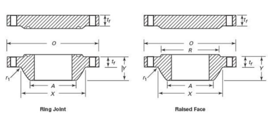
- Types Based on Face Types:1.Flat Face (FF) Weld Neck Flange,2.Raised Face (RF) Weld Neck Flange,3.Ring Type Joint (RTJ) Weld Neck Flange
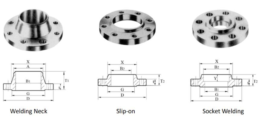
- Types Based on End Connections:1.Butt Welded Neck Flange,2.Socket Welded Neck Flange,3.Threaded Weld Neck Flange
Balingsteel Offers You Different Types of Flanges, Please Contact Us for the Latest Quotation!
Welded Neck Flange Manufacturing Process:

Material Selection:
Procurement of raw material for forging according to customer’s material requirements.
Cutting and Shaping:
Cut the raw material into standard sizes and forge the initial shape of the flange.
Heat Treatment:
Perform heat treatment, such as annealing, normalizing or quenching, to improve the mechanical properties of the material and eliminate welding stress.

Mechanical Processing:
Perform mechanical processing such as turning, milling, drilling, etc. on the flanges.
Inspection and Testing:
Appearance inspection of the flanges, non-destructive testing (such as ultrasonic testing, ray testing, etc.) to ensure that the flanges can withstand the design pressure.
Surface Treatment:
The surface of the flanges is treated according to the contract requirements, such as sandblasting, painting, galvanizing or chroming.
Marking and Quality Control:
Marking and final inspection of finished flanges according to customers’ requirements.
Packing and Storage:
Pack the flanges properly and put them into finished goods warehouse waiting for shipment.
For More Product Information About the Welded Neck Flange, Please Contact Us.