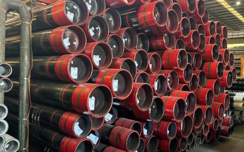
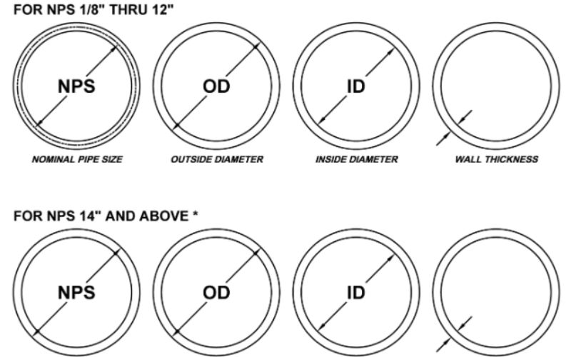
- Surface, External fusion-bonded epoxy on steel pipe
- Defect – a break in the film that provides a path to the steel
- First action – mark the indication and record joint, position and inspection stage
- Release evidence – original inspection, approved disposition and any required retest
A patch of pinholes caught before dispatch and a scratch found after unloading can both trigger the same holiday detector. To work out what causes FBE coating holidays, compare the marks with the last valid inspection. Mill defects often point the investigation to surface preparation and powder application. A fresh gouge at a support point sends it to the handling records.
FBE coating holidays occur when pinholes, missed coverage, cracks or mechanical damage provide a path through the epoxy to steel. Map where the detector responds and compare that location with the last test that covered it.
- A pore contained within the coating can leave the insulating barrier between the surface and the steel intact.
- Repeated indications at the same position across joints call for a line setup check.
- The repair record brings together the original finding, the approved repair and the documented retest.
What is a holiday test for pipelines?
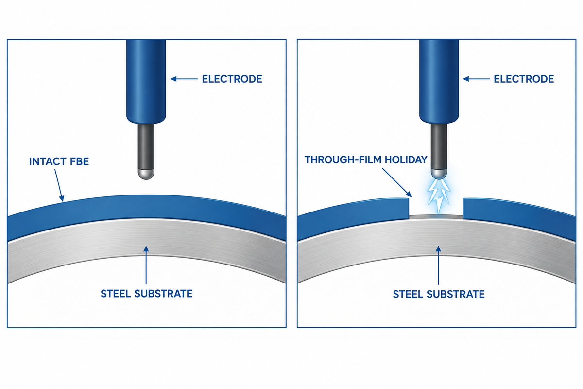
A holiday test checks the continuity of protective coatings used on pipelines. An electrode scans the coating. The detector is used to find a path through the nonconductive film to the conductive substrate and signals its location. This gives the inspector a point of interest. Dry film thickness readings, adhesion checks and pressure tests address build, bond and the pipe itself.
ASTM G62 describes low-voltage wet sponge testing and high-voltage spark testing for pipeline coatings. Holiday testing is performed at the stages listed in the project inspection plan. The approved inspection method determines the electrode and test voltage. The operator records film thickness in the required units, which may be microns, along with the surface condition and instrument checks.
If a signal occurs only on a wet coating surface or near bare steel at the cutback, check the setup and repeat under the approved conditions before ordering a repair. An insufficient test voltage or missed scan may leave a coating break undetected. An unsuitable high-voltage setting can damage a film. Record the surface condition and the instrument check so a subsequent inspector can perform the same test.
Why FBE coating develops pinholes at the mill
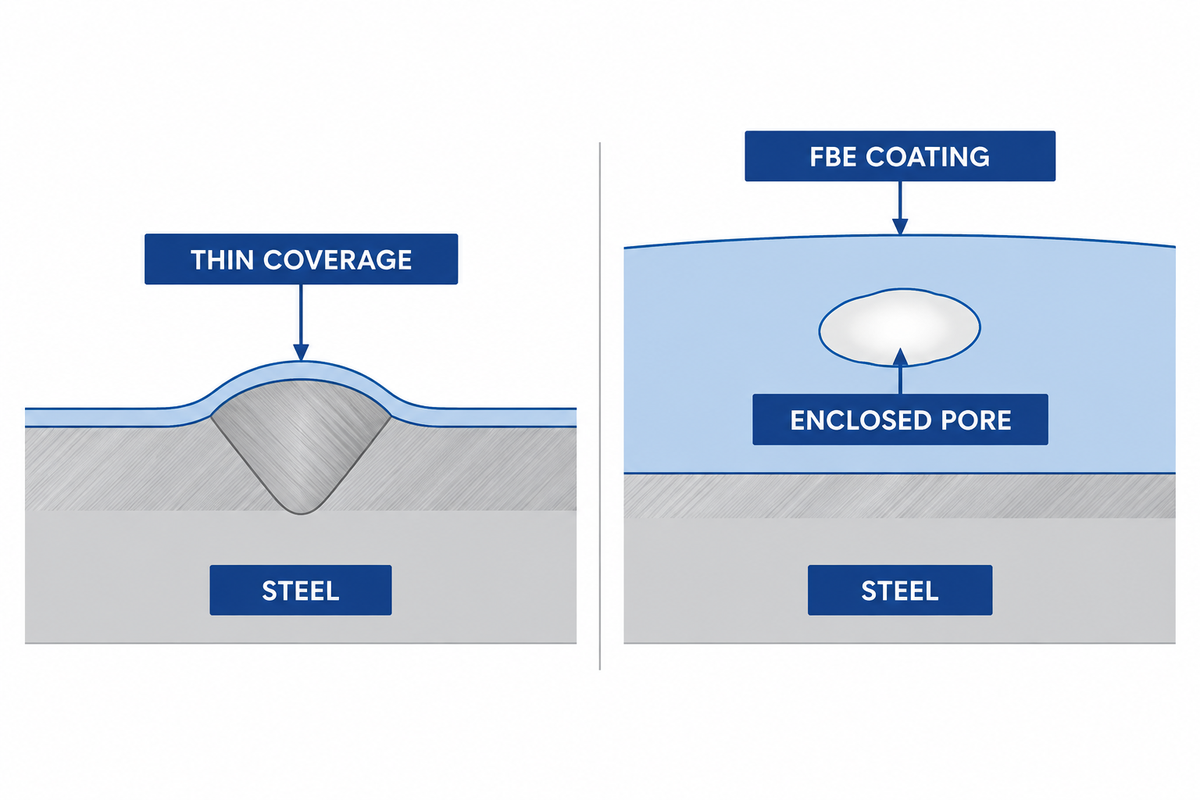
Pinholes can appear where powder coverage is incomplete, and outgassing from steel can contribute to porosity. Contamination can interfere with wetting, and uneven powder delivery can result in an area being barely covered. A clean, profiled surface supports coating quality by giving the powder a consistent surface to wet. Surface preparation, steel temperature and the curing process are covered as quality control checks for powder coatings in AMPP’s FBE application guide.
Rounded pores scattered over several joints prompt QA to check the powder lot, storage and air supply. A narrow strip following the weld seam calls for local thickness readings and a review of the spray pattern and seam profile. Compare the suspect area with an adjacent area. Average coating thickness for the joint may conceal a narrow strip with inadequate coverage. A visible void is suspect and warrants further investigation. Treat the void as a possible discontinuity until inspection establishes its depth or continuity.
Look at the defect before assigning a mechanism. In one KTA laboratory investigation of a two-layer FBE coating, polished sections showed pores within the applied film. The team performed holiday testing and microscopy to verify that a separate crack after field bending reached the steel. The combination of tests allowed the investigators to distinguish similar-looking conditions.
Where handling can damage coated pipe
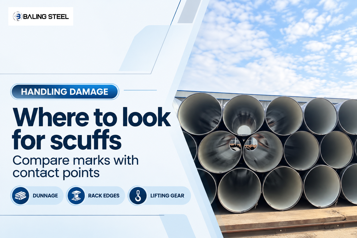
Dunnage, rack edges and lifting gear can scrape cured epoxy where they contact the pipe. Look for long, thin scuffs and chips that follow the contact shape. A mark near the pipe end may sit next to the planned bare cutback. Check its position against the drawing before considering it a coating defect. Damage that breaks the film leaves the steel exposed to the environment. Localized corrosion is of major concern where corrosion protection has been compromised.
US PHMSA inspectors have identified problems with coating damage and detector set up on pipeline construction inspections. After pipe has moved, a mill report may help date an indication only if it covers the same joint and area with a valid method. If the report indicates that the entire coated surface passed, check what the inspector recorded at the cutbacks and supports. An unrecorded strip leaves the damage window open.
Keep photos from dispatch and receiving under the same joint number. Include a close-up photo showing the mark’s position relative to the pipe end or seam and a wider photo showing the rack or spacer. Before the next move, record any intermediate storage and handling. This record lets the mill and site teams compare evidence while the load arrangement is still known.
How to tell a mill defect from handling damage
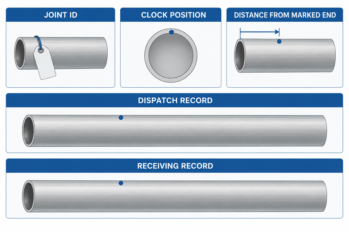
Matching indications before the dispatch point the investigation towards the coating line. A gouge that first appears at the receiving point and lines up with a spacer points to handling. Use the most recent valid test covering the same location, along with the joint number, distance from a marked end and clock position, to compare the two inspections.
| Indication type and pattern | Check first | Record to compare | Next action |
|---|---|---|---|
| Rounded indications across joints in a coating run | Powder and surface preparation | Batch, air supply, blast profile and cure logs | Compare affected joints with the previous and next run |
| Indications follow the longitudinal seam | Local film coverage and seam geometry | Thickness around the seam and spray positions | Map the same sector on joints from that setup |
| New gouge aligns with a support edge | Loading, transport and unloading contacts | Dispatch map, receiving photos and dunnage positions | Hold affected joints and inspect matching contact points |
| Indication appears inside a coated girth-joint overlap | Field application or repair conditions | Joint preparation, batch, cure and overlap records | Route the joint to field coating inspection for disposition |
| Crack opens on the outside radius of a field bend | Bending and the condition of the applied film | Bend sequence, local film thickness and inspection times | Extend checks to other bends made under the same conditions |
| Coating chip next to a bevel or cutback | Actual cutback boundary and end contact | Cutback drawing and dispatch images | Confirm where the specified coating starts before mapping a defect |
| Surface blister without a repeatable detector alarm | Film condition and adhesion | Preparation records and the appearance of the blister and surrounding film | Escalate for assessment under the coating specification |
| Alarm returns at the edge of a cured repair | Patch boundary and coverage | Original defect map, repair material and cure record | Keep the repair open and apply the specified reinspection procedure |
| Signal changes with surface condition or detector setup | Test repeatability and scan coverage | Detector verification, ground connection and location | Repeat under the approved inspection conditions |
The team can group joints by the process or contact they share. A seam pattern across a coating shift suggests checking that shift. Matching scuffs on one stack suggest checking other pipes at those support points. Evidence may fit more than one explanation. Keep the issue open until the inspections narrow the time and location. Readers requiring the full coating process can refer to the fusion bonded epoxy coating basics.
Which standards cover coating, field joints and repair?
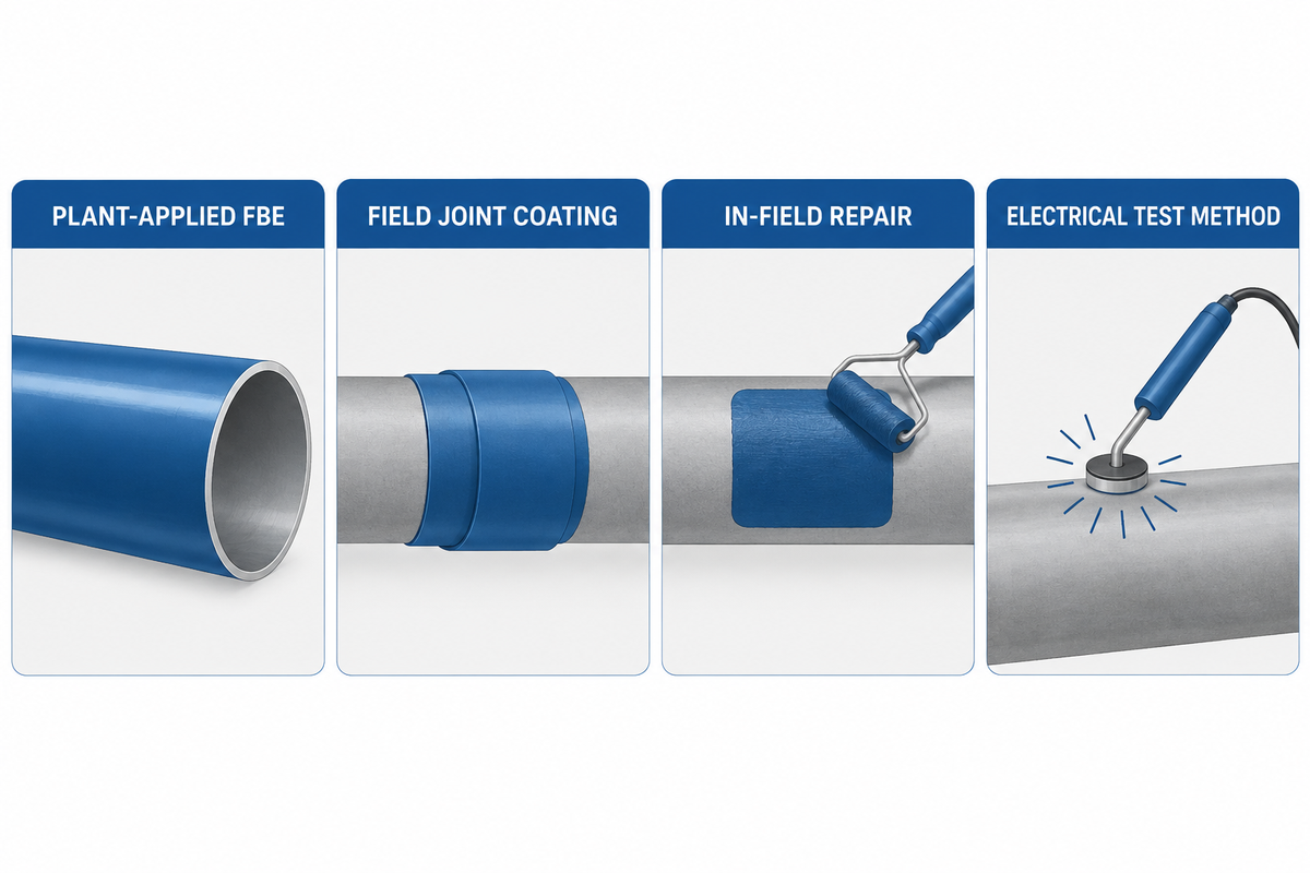
ISO 21809-2:2026 covers plant-applied external single-layer FBE for steel pipeline transportation systems within its oil and gas scope. ISO 21809-3 covers field joint coatings in its scope. ISO 21809-11:2019 covers in-field application, repair and rehabilitation for buried pipelines within its scope.
| Stage | Document | What to specify |
|---|---|---|
| Plant-applied single-layer external FBE | ISO 21809-2:2026 | Coating qualification and mill inspection scope |
| External coating at welded field joints | ISO 21809-3 | Joint system qualification and inspection points |
| In-field coating repair or rehabilitation on buried lines | ISO 21809-11:2019 | Approved repair procedure for the application |
| Electrical testing for coating discontinuities | ASTM G62, when specified | Applicable method, setting and test record |
Identify the multilayer system by its actual construction in the purchase specification. The project may also cite a NACE or AMPP document. Read its scope and the inspection plan alongside the coating application specification. Single-layer FBE coating systems and multi-layer systems such as three-layer polyethylene (3LPE) may have different coating thicknesses and acceptance procedures.
For U.S. gas pipelines subject to Part 192, 49 CFR 192.461(c) requires inspection just before lowering and backfilling and repair of damage detrimental to effective corrosion control. In the purchase order, specify separate responsibility for mill, receiving and field inspections so each of the three stages has an owner.
When can an FBE coating holiday be repaired?
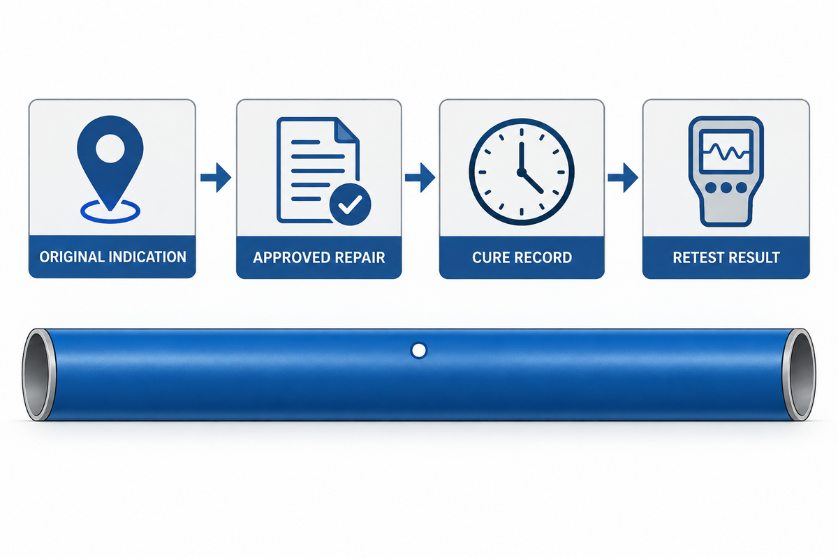
A local repair may be acceptable when the purchase specification permits it, the defect is within approved repair limits, and the inspector records the required results after cure. For in-field coating repair or rehabilitation on buried petroleum or natural gas pipelines, check the scope of ISO 21809-11:2019 against the approved project procedure. A repeating pattern across joints calls for holding the affected group while the cause and extent of the indications are determined.
Hypothetical receiving case. Joint J-A shows a gouge at a spacer position. Joint J-B and adjacent pieces show a run of marks by the seam. The joint identifiers are fictitious.
- Receiving: Photograph the location and retain the joint ID, inspection date and last inspection outcome.
- QA: Compare J-A to the dispatch record and to other joints at the spacer position. Check application records and local thickness on the group with seam indications.
- Disposition: Send J-A through the approved local-repair procedure if permitted. Keep the seam group on hold until the extent is known.
- Release: Link the repair material, cure record and specified retest results to the original joint ID. Record re-test before releasing the joint.
An electrical result on its own can’t verify good adhesion. When the specification requires adhesion or cathodic disbondment testing, keep those results separately. Cathodic protection (CP) is commonly used with external coatings on buried steel pipelines. Keep CP design separate from the repair acceptance record.
Ask the supplier to provide a quote for the repair and retest work separately when dealing with damage that delays release. The project team can compare the repair work and schedule impact with recoating, replacement or extra inspections. Keep the original failed indications in the report so the purchaser can evaluate repeated faults even after a clean retest.
What to request when ordering FBE coated pipe
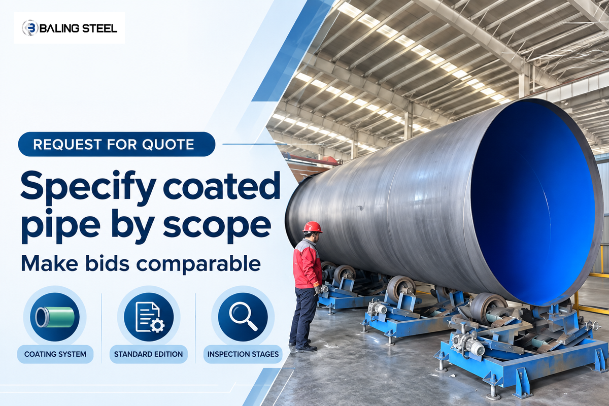
Baling Steel lists external FBE coated steel pipe. For product options when preparing the inquiry, see the coated steel pipe selection guidance. Specify the application, steel grades, pipe outside diameter, joint length, coating system, standard edition and required inspection stages so quotes cover the same scope.
The test sheet is one part of a release package. Before ordering, take a look at a sample hold-point report that connects a joint ID to a coating lot, test method, voltage and defect locations, repair disposition and retest results. Agree which company will sign the factory release and which team takes over receiving inspection.
After repair, recheck the joints and arrange a handoff to the receiving team for joints that pass. With the original map and retest result, the receiving team can distinguish a new damage report from a repair already accepted at dispatch. This comparison makes it easier to release unaffected stock and keep the inspection crew available for the suspect group.
Frequently asked questions
Does a pinhole always mean the steel is exposed?
A pore can terminate inside the epoxy. A pinhole that penetrates the coating exposes steel and calls for holiday testing of the surrounding area. Inspect the surface and map any repeatable electrical indication using the approved procedure. Widespread porosity in the coating may warrant a QA investigation into the coating process, even if individual pores give no alarm.
Can FBE coated pipe pass its mill test and fail at delivery?
Yes, the mill report explains the condition of the pipe when it was tested. Contact points change with loading, movement of dunnage and unloading. Use the joint number and position of the defect to check dispatch and receiving documents. An inspector looks for leads when a scratch aligns with a rack edge. The inspector does this before the pipe moves again.
Does a repaired holiday automatically make a pipe joint acceptable?
The joint still must meet the governing specification. Release requires an approved repair within the specified limits, full cure and the required reinspection records. An isolated defect may be repairable under those terms. Defects recurring at matching positions across several joints warrant a wider check before release. Link the first inspection record and the retest results to the same joint so the purchaser can verify both before release.
What is a holiday test of coating intended to find?
The test finds breaks that let the current reach steel. Report any other dry film thickness measurements along with the electrical results.
Why is it called holiday testing?
The inspection is called holiday testing because it identifies holidays, the gaps left in the coating. That includes a missed patch or a cut through a cured film.
What are FBE coatings?
Fusion bonded epoxy coatings form when epoxy powder melts and cures on heated steel. FBE can serve as a standalone coating or as a layer in a larger system.
References & Sources
- ASTM International, pipeline coating holiday detection methods
- AMPP, FBE application and inspection challenges
- KTA, failure investigation of cracked FBE coating
- PHMSA, pipeline construction inspection findings
- ISO 21809-2:2026, plant-applied single-layer FBE
- ISO 21809-3, field joint coatings
- ISO 21809-11:2019, in-field coating, repairs and rehabilitation
- United States, 49 CFR 192.461, external protective coating