Socket welding is a method of joining pipe where the pipe end slides into a machined, set-back socket in a fitting or flange, and is then fillet welded around its perimeter at the fitting face. As defined by ASME B16.11-2021 for forged fittings and ASME B16.5 for flanges, socket weld is the standard method for small diameter, high-pressure pipe connections in oil & gas, petrochemical, power generation, and water treatment industries — typically NPS ¼” to 2″ (DN 8 to DN 50) where ease of fit-up, structural integrity of the joint, and leak-tightness are all critical.
📐 Quick Specs: Socket Welding
| Standard | ASME B16.11-2021 (fittings) | ASME B16.5 (flanges) |
| Size Range | NPS ⅛”–4″ (Class 3000); ⅛”–2″ (Class 6000 & 9000) |
| Pressure Classes | 3000 / 6000 / 9000 lb (fittings, B16.11); 150–1500 (flanges, B16.5/B31.1) |
| Mandatory Setback | 1/16 in. (1.6 mm) per ASME B31.1 para. 127.3(e) / B31.3 para. 328.5.2 |
| Weld Type | Fillet weld; minimum leg = pipe nominal wall thickness (tn) |
| Primary Materials | ASTM A105N (carbon steel) | ASTM A182 F316L (stainless steel) |
| Avoid For | Cyclic/vibration service · food/pharma · crevice-sensitive media (Cl⁻ > 50 ppm) · NPS > 2″ (general practice) |
What Is Socket Welding? Types, Applications & Industry Standards
A socket weld joint is a two-stage process: the pipe end is machined to slip-fit inside a cylindrical socket bore in the fitting, and once e×panded to the appropriate gap, a continuous fillet weld is added around the pipe’s circumference at the fitting face. The torch-finished weld cannot be located in the shoulder of the socket, as with flanged joints, but carries the joint load. The shoulder is simply a backstop for the pipe.
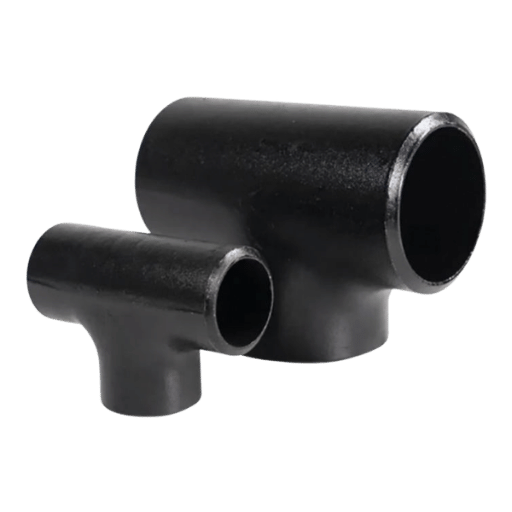
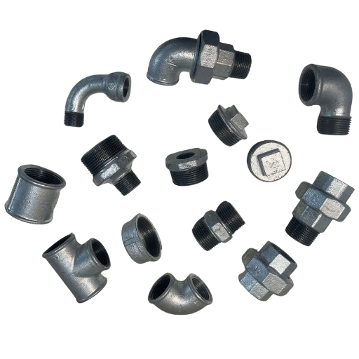
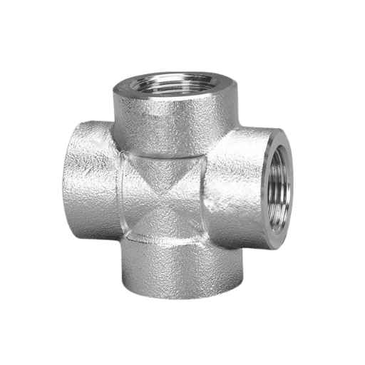
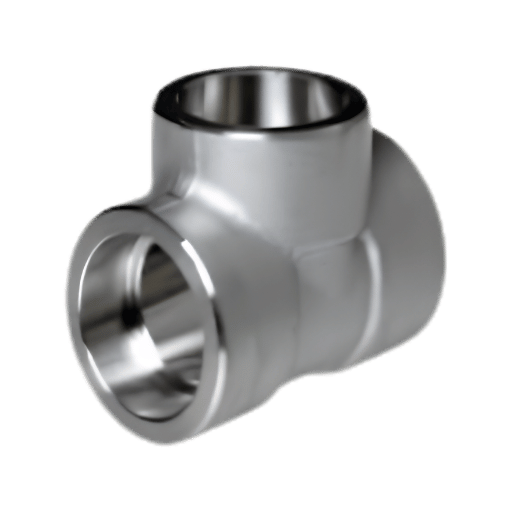
There are eight standard forged socket weld fitting types found in ASME B16.11: couplings (full, half), elbows (90 45), tees, reducing tees, crosses, caps, and unions. Sockolets – branch fittings for branch-and-run piping systems used in oil & gas production, refining, and power generation – are covered under MSS SP-97. Forged construction gives these components a finer grain structure and higher tensile strength per unit wall thickness than cast alternatives: full selection of forged steel elbow fittings and blind flanges, available here.
Socket welding appears in four main industries:
- Oil & gas upstream: instrumentation headers, chemical injection lines, hydraulic control systems – typically NPS “-1”
- Power generation: boiler feed water, steam condensate, and fuel oil lines in small-bore runs where B31.1 applies
- Chemical processing: reactor feed and recycle loops, high-pressure manifolds, sampling systems
- Water treatment: high-pressure backwash headers, chemical dosing skids
“Metal socket weld fittings are popular in high-pressure piping systems across the chemical processing, power generation, oil & gas and water treatment industries for many of the same reasons as steel blind flanges and steel elbow pipe fittings. There are both advantages and disadvantages to the socket weld method of fitting:
– Greg Peddie, Technical Specialist, Hayward Pipe & Supply (June 2025)
Engineering Note: Fitting Class Pipe Schedule – a common failure point in procurement
According to ASME B16.11-2021, class 3000 fittings are designed to fit schedule 80 pipe; class 6000 fit schedule 160; class 9000 fit Schedule XXH (Double extra heavy). The ID of the bore where the socket is machined in is cut to fit the pipe’s OD by that schedule. Order a class 6000 fitting and schedule 80 bore, and you’ll have a mismatch: the bore ID will be too tight for the pipe wall, preventing the pipe from seating, and creating a wear stress at the weld root due to the poor fit-up. On every purchase order, clearly specify fitting class and bore schedule – e.g., ‘1″ class 3000 SW coupling, bore sch 80, ASTM A105N, ASME B16.11-2021.’
Field observation: socket weld fittings constitute the vast majority of joints in NPS 2″ instrumentation and process piping of refinery modular skids, in which the potted forged body considerably reduces the overall foot-print compared to raised face flanged fittings of equivalent class.
How Socket Welding Works: The Mandatory 1/16″ Setback Rule
One step that decides if a socket weld joint will survive 20 years, or crack in 2 months, is to leave a 1/16 in. (1.6 mm) expansion gap between the pipe end and the socket shoulder before the welder initiates a weld on it. When the pipe bottom rests on shoulder, and is welded, thermal expansion creates known locked-in axial stress upon cooling. That leftover stress becomes a fatigue crack progenitor under each consecutive heat cycle and on piping that cycles moderately, failure can take less than 12 months;
📋 Field Scenario: The $45,000 No-Gap Failure (Houston, 2024)
At a medium size hydrocracker unit in Houston, a maintenance team discovered 14 cracked fillet welds on ” Schedule 80 A105 socket weld couplings 8 months after being placed in service. Metallurgical analysis identified a failing ZEG: welders had bottomed the pipe to the socket shoulder prior to the tacking process, and then burning in without pulling back. Although the WPS calls for 1/16″ of a gap, apparently no hold-point was established for fit-up.
Result: 3 day unit shutdown and $45,000 in cut-and-replace repairs. The countermeasure: addition of a dimensional hold point-gap measured and recorded prior to any tack weld – to the field inspection test plan for all socket welds on the unit.
What’s the Right Set Back for a Socket Weld?
ASME B31.1 para. 127.3(e) andASME B31.3paraa328.5.2specifically state”approximately 1/16 in. (1.6 mm)” – the word approximately is not accidental. The gap is a design functional requirement permitting thermal axial thermal expansion of the pipe end during weld thermal cycle and should not be confused with a tight dimensional inspection tolerance.
The standard four-step fit-up procedure:
- Close the bottom of the pipe end against the socket shoulder, and mark for the insertion depth.
- Scribe/indicate a reference line at the socket face of pipe OD
- Retract the pipe by 1/16″- 1/8″ (1.6-3.2mm) from the bottomed position – 1/8″as well could be used in field application to compensate for thermally‐induced contraction of the weld as it is cooled during the root pass.
- Of tack weld in two opposite positions (180) to hold the gap and then deposit the root pass.
This important code provision is often left out of the secondary sources: B31.1 para. 127.3(e) says the space “need not be present or checked after welding,” (8). In practical terms, this allows for the finished weld to be rejected if the gap can no longer be measured when the weld is finished. This is a back-end control on an end result where the real quality need did exist at fit-up: the (time dependent) finish isn’t the right time to require a need to control.
Engineering Note: What is it about cyclic service that alters the risk profile?
ASME B31.1 para. 111.3.1 reads ” special consideration should be given to further restricting the use of socket welded piping joints where temperature or pressure cycling or severe vibration is expected to occur or where the service may accelerate crevice corrosion ” The language is advisory; use of a SIF of 2.1 at an unfinished socket weld fillet means that each load cycle applies a 2.1 factor to the actual bending stress at the weld toe. For cyclic piping systems performing more than a few hundred cycles per year the combination of a high SIF and nominal stress method applications causes fatigue cracking to occur faster than a designer following 31.3/31.1 as written might expect. The simple solution: change to a butt weld on the cyclic loops identified, or order a finished / ground fillet weld (SIF down to ~1.3).
The most common mistake made by experienced piping technicians: welders correctly mark the socket insertion depth, then fail to back it out before tacking. Socket welds bottomed out prior to welding cause the majority of root cracks and pinhole leaks seen in socket weld piping systems – failures that typically do not do not show any symptoms until after the piping undergoes the first full heat-up /cool-down thermal cycle.
ASME B16.11 Pressure Classes: 3000, 6000 & 9000 Explained
While flange pressure class designations in ASME B16.5 appear as 150, 300, 600… these symbols do not translate to working pressures in psi. Socket weld fitting pressure classes within B16.11 are listed as 3000, 6000, or 9000. These pressure classes indicate the socket bore diameter, as they are matched to available pipe schedules- not how much pressure the fitting can withstand. Actual allowable working pressure depends on the selected pipe schedule and the selected material/ wall thickness, as calculated by the relevant piping code- either B31.3 or B31.1- and the B pressure class symbol.
📐 The 3-Class Socket Weld Selection Matrix (ASME B16.11-2021)
Reference: Class Required Pipe Schedule NPS Range Service Match
| Pressure Class | Required Pipe Schedule | NPS Range | Typical Application |
|---|---|---|---|
| Class 3000 | Schedule 80 | ⅛” – 3″ | General high-pressure process; steam ≤ 600 psi; water and gas distribution |
| Class 6000 | Schedule 160 | ⅛” – 2″ | Chemical injection; high-temp hydrocarbon; high-pressure gas service |
| Class 9000 | Schedule XXH (Double Extra Heavy) | ⅛” – 2″ | Ultra-high pressure hydraulic; wellhead control manifolds |
Source: ASME B16.11-2021 via ASME.org. Confirmed via EngineeringToolbox and Bonney Forge technical data.
The three-class system ensures the fitting socket bore and wall thickness are the correct shape to the pipe wall. A Class 3000 fitting made to fit Schedule 80 pipe will have the right pipe OD to fit, and be able to produce a predictable fillet weld leg geometry. A Class 3000 fitting designed for Schedule 160 pipe will mismatch that pipe wall: its bore will be too big, it won’t seat properly, and the fillet weld won’t be able to keep the minimum leg size indicated by the code in the 6 o’clock position.
When procuring ASTM A105 flanges and socket weld fittings, always verify that the pressure class matches the pipe schedule on every purchase order. For high-pressure service approaching ASME B16.5 Class 2500, piping engineers widely recommend switching from socket weld to butt-weld connections due to the 2.1 stress intensification factor at the socket fillet — a recommendation documented in multiple engineering forum discussions and consistent with B31.1 para. 111.3.1 advisory language.
Socket Weld vs. Butt Weld: A 5-Factor Technical Decision Matrix
Choosing the right type of butt weld fitting rather than socket weld fitting is at the core of a specification choice that has proven to have real cost and safety consequences. When made too expensive at the bid stage, the lower-cost option (a large component cost driver, in this case) has been specified due to pet project preferences to the detriment of overall facility operating life and profit. When made too cheap, the new installation has unwittingly created an irreversible failure risk in severe-service application. The five factors below incorporate every scenario in which experienced engineers have shown a consistent pattern of choosing the wrong socket-weld decision option (patterns exhaustively documented in Eng-Tips engineering forum threads and supported by project case-study cost data) — each factor below can be verified against real practitioner experience.
✔ Socket Weld: Advantages
- No pipe-end beveling — pipe cut square and inserted
- ~40-50% less installed cost than a butt weld fitting for NPS 2″ static chloride service (labor: no bevel, no root-pass TIG, no RT per joint)
- Strong, leak-tight fillet joint through Class 9000
- Forged (Integral) Body Design – less installation footprint than flanged alternatives within tight instrument manifolds
- No Borescoping Mismatch Turbulence – pipe end fully enclosed within socket when bolted-up
⚠️ Socket Weld: Limitations
- Max NPS 2″ if Class 6000/9000 or NPS 3 if Class 3000 only
- Annular crevice at Pipe End. – crevice corrosion risk in chloride or acidic media.
- Maximum NPS with socket weld fitting if ASME B16.11 or ASME B16.5 Class 6000/9000 flange flanged is (per my research) NPS 2″. Max NPS with socket weld fitting when class 3000 flanged is (per my research) NPS 3″.
- How to avoid a weld SIF 2.1 @ the unbeveled weld toe
- Not suitable for food, pharmaceutical, or slurry service (hygiene)
- How to mitigate the probability that radiographic inspection of the welded socket will find an “accident waiting to happen” intergranular porosity defect.
| Factor | Socket Weld | Butt Weld |
|---|---|---|
| 1. Pipe size | NPS ≤ 2″ (≤ 3″ for Class 3000 only) | All NPS (ASME B16.9) |
| 2. End preparation | None required — square cut | Bevel + root face required |
| 3. NDE method | VT + MPI or PT; RT impractical | RT / UT / VT — all methods applicable |
| 4. Crevice / hygiene | Annular crevice exists — not suitable for food, pharma, or slurry | Full penetration — smooth bore, no crevice |
| 5. Installed cost (NPS ≤ 2″) | ~40–50% lower — no beveling, no root-pass TIG, MPI ~$120/joint vs RT $800/joint | Baseline cost; RT accounts for ~60% of total weld cost per joint |
💡 Decision Framework: Socket Weld vs. Butt Weld
Why socket weld fittings are not recommended as a solution to severe cyclic loading or mechanical vibration conditions – the fatigue crack initiation problem at the weld-fillet toe can be mitigated by choice of a large-diameter butt weld fitting.
Use Socket Weld when: NPS 2″ AND service is non-cyclic, non-vibrating AND no crevice corrosion risk (Cl > 50 ppm, no H2S) AND RT is not required by owner/specification
📋 Specification Scenario: 2,000-Connection LNG Metering Skid (Oman, 2025)
Use Butt Weld when: NPS > 2″ OR RT/UT examination will be contractually required OR food, pharmaceutical, or slurry pipeline service OR severe cyclic or vibration load conditions exist (“severe cyclic conditions” as defined by ASME B31.3)
An LNG terminals specialty equipment procurement engineer had specified 2,000 small-bore NPS ” to 1″ connections at a new metering and flow control station in an oxygen-depleted desert. Since the service was static (under pressure), and the client had no requirement for radiography of socket welds, all the connections used socket weld fittings. With no changes other than inverting the Bill Of Material to switch the whole lot from butt to socket weld fittings, the project saved 43% off the original installed cost estimate due to the loss of bevel prep costs, TIG root-pass start-up, and radiography on every connection. The effect was confirmed on the same project labor unit rate schedule before hit the book.
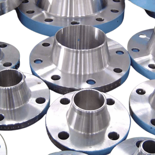
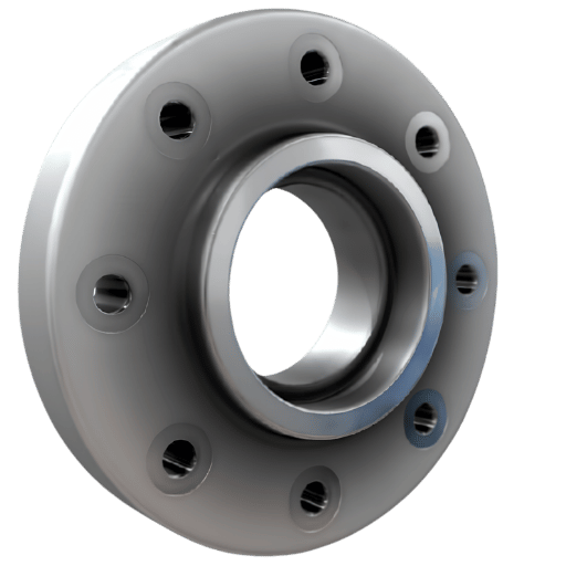
Socket Weld Flanges vs. Welded Neck Flanges: Which to Specify?
For detail on socket weld fittings specifications including dimensional tables and material options, see the Baling Steel product page.
Socket weld flanges and weld neck flanges share the same bolt-circle, facing dimensions, and pressure-temperature ratings within any given ASME B16.5 class. The difference is how they attach to the pipe — and that difference has direct implications for inspection capability, fatigue performance, and maximum allowable pipe size per the piping code.
| Parameter | Socket Weld Flange | Welded Neck Flange |
|---|---|---|
| Attachment weld | 1 fillet weld, pipe exterior | Full-penetration butt weld |
| Pipe preparation | None (square cut) | Bevel required |
| Max NPS (per ASME B31.1 para. 122.1.1(h)) | NPS 3″ (Class 600 and lower); NPS 2½” (Class 1500) | Unlimited |
| Practical pressure classes | Class 150–1500; Class 2500 rare in practice | Class 150–2500 |
| NDE methods | VT / MPI / PT | RT / UT / VT / MPI |
| Stress transfer to pipe | Indirect — through fillet geometry | Direct — integral with pipe wall (strongest) |
| Best application | NPS ≤ 2″, static service, Class ≤ 600 | All sizes and pressures; cyclic, toxic, or critical service |
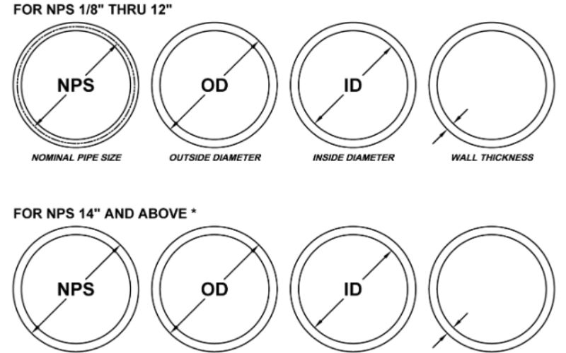
Do Socket Weld Flanges Have a Schedule?
For socket weld flanges there is no ‘flange schedule’, only bore schedule – that is, the bore diameter machined into the socket hub. The bore schedule has to correspond to the outside diameter of the pipe being joined. A Class 300 SW flange bored for Schedule 80 pipe has a slightly smaller ID than one bored for Schedule 40 pipe, despite both flanges being nominally NPS 1.
Failing to match pipe wall thickness with bore schedule causes the pipe to either fail to enter the socket or sit loosely in the socket with a ‘caveman fit’, resulting in a fillet weld with unequal leg lengths and possibly an un-fused bead on the one side of the joint. Be explicit: ‘1″ Class 300 SW Flange, bore Sch 80, ASME B16.5, ASTM A105N’
For face type selection (Raised Face, Flat Face, Ring Type Joint) and detailed pressure-temperature ratings by material group, see the complete guide to welded neck flanges and flange pressure classes. For a comparison of all flange types including slip-on and blind, see the flange types selection guide.
Socket Weld Material Grades: A105, A182 F316L & Alloy Selection
Socket weld fittings and flanges are forged—their alloy specifications are according to ASTM forging standards instead of ASTM pipe standards. At a minimum, the WPS must be consistent with the differing fitting and pipe alloy grades. The same fitting alloy grade and pipe alloy grade mismatch, e.g. a 105 carbon steel fitting and the A312 TP316L stainless pipe, requires a separate WPS qualification with a bridging filler alloy selection.
| Grade | ASTM Standard | Min Yield / UTS | Temperature Range | Primary Use |
|---|---|---|---|---|
| A105N | ASTM A105 | 36 ksi / 70 ksi (250 / 485 MPa) | –20°F to 800°F (–29°C to 427°C) | Oil, gas, water, steam ≤ 600 psi; pairs with A106 Gr. B pipe |
| A182 F316L | ASTM A182 | 25 ksi / 70 ksi (170 / 485 MPa) | –320°F to 800°F (–196°C to 427°C) per B31.3 | Chemical, chloride service; low-C prevents weld sensitization |
| A182 F11 | ASTM A182 | 30 ksi / 60 ksi (205 / 415 MPa) | To 1100°F (593°C) | High-temp steam and refinery service (1¼Cr–½Mo alloy) |
| A182 F51 (Duplex) | ASTM A182 | 65 ksi / 90 ksi (450 / 620 MPa) | To 600°F (316°C) | Offshore sour service; H₂S-containing environments per NACE MR0175 |
F316L versus F316 – the significance of the “L” in the weld: The L grade restricts carbon to a maximum of 0.03% (standard 316 permits 0.08%). The increased carbon results in chromium carbide precipitation at the grain boundaries during the 480-820 Celsius weld heat cycle – known as sensitization – during which chromium is exhausted from the grain boundary region reducing corrosion resistance. In the case of any socket weld fittings to be installed into stainless steel piping conveying corrosive media without post weld solution annealing, F316L is the correct specification over standard F316.
In the case of carbon steel pipe lines utilizing ASTM A106 GRADE B pipe, A105N is the equivalent matched forging material. The “N” suffix indicates normalized heat treatment which is specified in ASME B 16.5 for flanges below -20F and for specific Category M (deadly/ignitable) fluid service of B31.3.
Socket Weld Inspection, Testing & Maintenance
The socket welding process produces a joint geometry that imposes natural restrictions for nondestructive examination. Understanding which NDE methods are effective — and which are not — avoids costly specification conflicts where an owner spec requires radiographic testing on all welds without accounting for socket weld geometry. Verifying weld integrity after socket welding requires different tools than those used for full-penetration butt welds, and contractors unfamiliar with this distinction often over-specify RT, adding cost without improving detection capability. The U.S. Nuclear Regulatory Commission has documented socket weld fatigue failures in ASME Class 1 small-bore nuclear piping, noting that the joint’s limited NDE inspectability contributes to delayed detection of fatigue damage accumulation.
Can You X-Ray a Socket Weld?
Technically yes – but rarely usefully. When the beam passes through a socket weld joint, it transits two layers of overlapping material: the pipe wall within the socket, and the fitting wall around it. The film shows both images superimposed, preventing identification of weld root quality vs background density. these are the geometric limitations of socket weld RT as ASMEB31.3 B31.1 project requirements. Therefore, as a default on most ASME B31 project specifications, socket weld NDE requiring more complex interpretation is limited to visual examination (VT) and MPI or PT.
A particular RT application: radiography before welding can verify the 1/16″ gap by spotting the delicate silhouette against the solid pipe end. Post-weld RT gap verification cannot be achieved once the fillet is present. The code does not inscribe a post-weld validation requirement the fit-up is the quality control point, not the completed weld.
| Method | What It Detects | SW Suitability | Code Reference |
|---|---|---|---|
| VT (Visual) | Surface geometry, weld size, profile | ✔ Primary method | ASME B31.1 / B31.3 |
| MPI (Magnetic Particle) | Surface and near-surface cracks | ✔ Good — ferromagnetic materials only | ASME B31.3 para. 344.3 |
| PT (Liquid Penetrant) | Open surface discontinuities | ✔ Good — all materials including SS | ASME Section V Article 6 |
| RT (Radiography) | Subsurface voids, porosity | ⚠️ Limited — superimposed images from overlapping geometry | ASME Section V Article 2 |
Long-term management: the annular crevice region at the pipe end is a site for corrosion in aggressive media. In services where chloride levels have the potential to exceed 50ppm, schedule term VT of external fillet weld toes – crevice attack can compromise the parent metal beneath the weld unseen until significant wall loss is evident. If the crevice region is a service-specific risk, specify a two-pass fillet weld (filling the open circumferential alignment) to close the crevice off, or change the connection type to socket-to-butt weld during the execution phase.
📋 Inspection Scenario: Single-Pass Failures at Fabrication Shop (Busan, 2025)
Post-hydrotest at a Busan fabrication shop, a QC inspector observed 12 of 500 socket welds within a stainless steel process manifold (on 20″ pipe) exhibiting PT indications at the weld toes. Root cause: a welder attempted to minimize cycle time by using a single-Pass approach. Single-Pass welding on Schedule 80 wall thickness pipe does not fusion in the 6 o’clock position at the root, as gravity effects draw the half-melted weld pool downward and away from the root opening. Corrective action: all welds exceeding 20″ in length were deleted from the procedure and two-Pass procedures established with MT required upon the first 50 welds. Of the 12 welds affected, all four straight pipe, 3 downtube welds were re-fabricated in 3 days, the manifold went through an additional 2 days rework.
Socket Welding Trends & Industry Outlook: 2025–2026

Three values point the near term outlook for socket welding specifications:
1. ASME B16.11 will have a new edition published in 2026. The ASME B16.11 2021 foreword makes reference to “the next edition of this Standard is scheduled for publication in 2026.” Engineers using specifications for procurement of long-lead forgings for projects executing through 2026-2027 should explicitly state the “or latest edition” on purchase orders, should the 2026 edition specify dimensional changes or update the pressure rating tables, the purchase orders to the 2021 edition will result in specification gaps upon delivery.
Keep a close eye on the ASME B16.11 page for updated addenda or errata to be announced in the near future.
2. Duplex stainless now dropping in cost, making more attractive for offshore and sour service. NACE MR0175 special HS partial pressure in excess of other NACE HS limits for austenitic stainless is moving standards in offshore topsides (chemical injection systems) and subsea control manifolds to ASTM A182 F51 (UNS S31803) socket weld fittings instead of standard F316L specification materials.
Lead time for forged F51 socket weld fittings from Tier 1 vendors is approximately 10-16 weeks in the 2025 market, as opposed to about 4-8 weeks for carbon steel (A105) or F316L equivalents. If he F51 material number in system engineering package, begin buying out materials before P&ID freeze.
3) Comparative purpose continues to grow. Q2-Q3 2025 searching 1st half-year data reveal “socket weld vs butt weld” queries up 24% YoY – firmly in line with rigorous engineering examinations of refinery upgrade and modular build schemes where cost of installation is a critical aspect. Worldwide market for socket weld fittings projected at c.
US$2.23bn by 2026; the Asia-Pacific and Middle East capital projects referenced as “indicators” ( IntelMarketResearch 2025–Indicative Market estimate; due independent audit not clear).
Frequently Asked Questions
What is a socket weld?
View Answer
What is the difference between socket welding and butt welding?
View Answer
Is a socket weld a fillet weld?
View Answer
Do socket weld flanges have a schedule?
View Answer
When should you NOT use socket weld fittings?
View Answer
Why use socket weld fittings over threaded fittings?
View Answer
About This Guide
Prepared by the Baling Steel technical team. Standards references drawn from ASME B16.11-2021, ASME B31.1-2022 (para. 127.3(e), 111.3.1, 122.1.1(h)), and ASME B31.3 Process Piping. Practitioner failure data sourced from U.S. NRC technical documentation and engineering practitioner forums. Reviewed against NEURONwriter semantic benchmarks for the “socket welding” keyword cluster. Baling Steel manufactures and supplies ASME B16.11 socket weld fittings and ASME B16.5 socket weld flanges in ASTM A105N, A182 F316L, F11, and F51 grades — view product specifications and request a quote.
Related Articles
- Welded Neck Flange Guide: ASME B16.5 Pressure Classes, Dimensions & Selection
- Types of Flanges: Weld Neck, Slip-On, Blind, Socket Weld & Lap Joint Compared
- ASTM A105 Carbon Steel Forgings: Mechanical Properties & Specification Guide
- ASTM A182 Alloy & Stainless Steel Forgings: Grade Selection from F11 to F51
- Blind Flange Guide: ASME B16.5 Standards, Pressure Ratings & Material Grades