Updated August 2026 · Engineering and procurement guide
A slip blind is a removable solid line blank installed between two mating pipe flanges to stop the flow path. It’s also called a paddle blind, spade, or line blank. Buyers use it as a positive physical barrier, but the component doesn’t replace an approved energy-control procedure, an engineered piping review, or the governing project specification.
Specify a slip blind by the applicable standard or approved drawing, nominal pipe size, mating-flange class and face, material, design pressure and temperature, intended duty, marking, inspection, and document package. Never select one from pipe schedule or a copied thickness chart alone.
Quick Specs
| Primary public standard scope | ASME B16.48-2025 operational line blanks |
|---|---|
| Published nominal size range | NPS 1/2 through NPS 24 |
| Published class designations | 150, 300, 600, 900, 1500, and 2500 |
| Mating flange basis | ASME B16.5 flanges within the B16.48 public scope |
| Common companion | A matching spacer for the open-line condition |
| Selection basis | Standard table, purchaser drawing, or verified engineering calculation |
Scope values are summarized from ASME’s public standard page. Obtain the licensed standard for controlled dimensions, tolerances, ratings, and tables.
- A product name isn’t a specification. Include the flange basis, class, face, material, duty, and documents.
- Pressure class is a designation, not one universal allowable pressure for every material and temperature.
- Maintenance isolation and hydrostatic-test duty aren’t automatically interchangeable.
- Company certificates or laboratory claims don’t prove conformity of a particular production lot.
What Is a Slip Blind? How It Works and What It Is Not
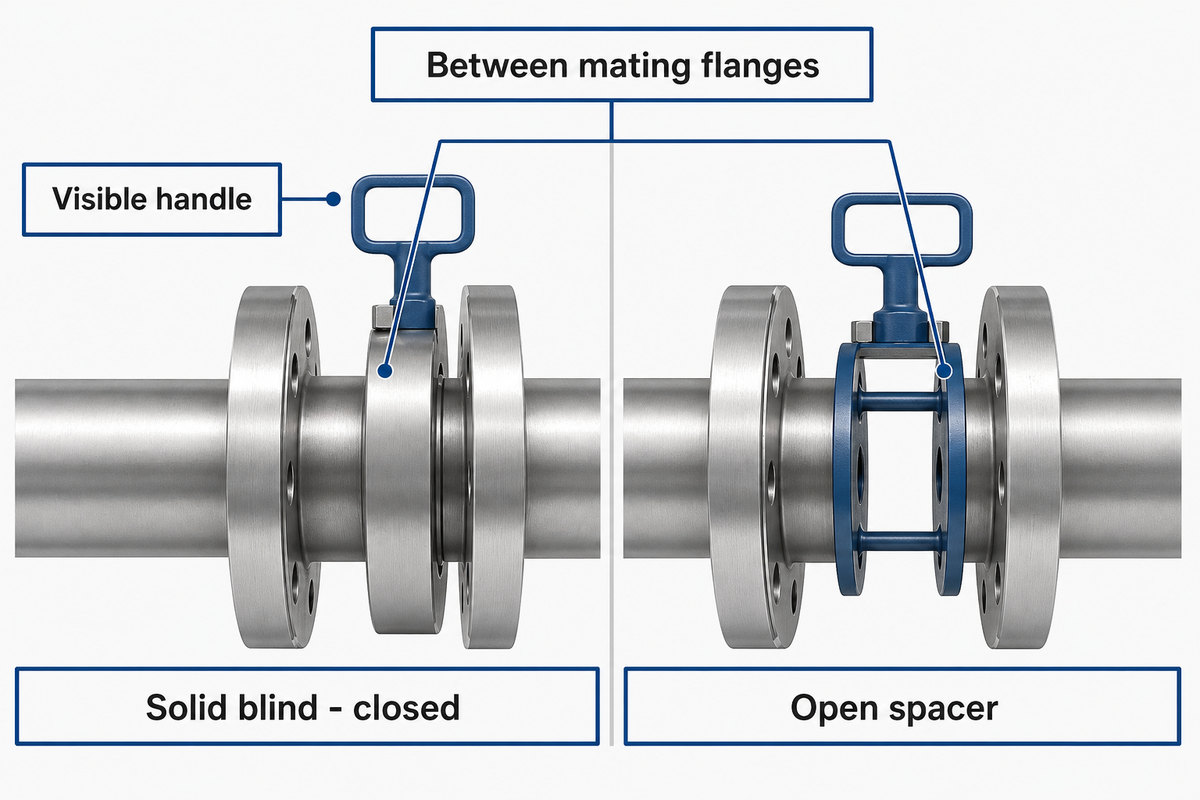
A slip blind blocks process piping by placing a solid metal disc or plate across the flow bore between two pipe flanges. That physical distinction comes before company certificates or production-lot claims. Its handle remains visible outside the joint for identification and handling. Because the arrangement is removable, it suits a process line that must alternate between an open spacer and a closed blank under controlled conditions.
Terminology Firewall
The Terminology Firewall separates similar names before they create a wrong purchase order. “Paddle blind,” “spade,” “line blank,” “pancake blind,” and “slip blind” may refer to the same solid handled component. Project vocabulary still controls, so attach a drawing and state the standard rather than trusting the name alone.
Do not confuse it with a slip-on flange welded to pipe. It is not an orifice plate used to meter flow. It is also not a blind flange with bolt holes around its perimeter. Its companion spacer, sometimes called a paddle spacer, has an open bore and preserves the same installed gap when the line is returned to service.
- Use the project name and component drawing together.
- State whether the required item is the solid blind, the spacer, or a matched set.
- Confirm the visible handle and marking requirements.
- Write “slip flange” without clarifying the component.
- Assume a product photo proves class, material, or duty.
- Substitute a blind flange without a piping-design review.
ASME B16.48 Scope and the Specification Fields That Matter
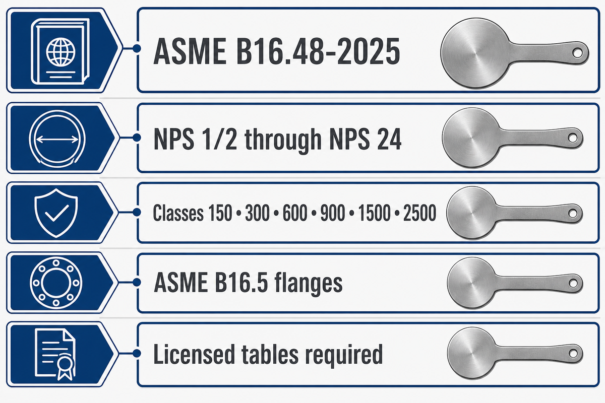
ASME B16.48-2025 gives the public scope for operational line blanks installed between ASME B16.5 flanges from NPS 1/2 through NPS 24 in Classes 150, 300, 600, 900, 1500, and 2500. Its scope covers ratings, materials, dimensions, tolerances, marking, and testing, but controlled tables remain in the licensed standard.
Standard Scope Guardrail
The Standard Scope Guardrail prevents a scope summary from being misread as a finished design. Start by confirming that the component, flange family, size, and class fall inside the edition named by the project. ASME’s separate B16.5-2025 public scope shows why the mating-flange basis matters: coverage isn’t identical for every class, size, and component.
Treat the ASME B16.48 line-blank standard page as a scope check, not as permission to copy a dimension from another project. If a size, flange standard, pressure class, or configuration lies outside that scope, the purchaser needs an engineered specification and an approved drawing.
Line-Blank Interface Lock
The Line-Blank Interface Lock records the flange interface, isolation state, duty, and evidence needed to identify the intended slip blind. Before a supplier fixes the design or price, the record should answer the following 12 questions.
| Specification category | What the buyer must state | Why it controls the order | Limitation if missing |
|---|---|---|---|
| 1. Standard and edition | Example: ASME B16.48-2025, if applicable | Fixes the controlling scope and tables | Supplier may quote a different basis |
| 2. Nominal pipe size | NPS or DN, clearly identified | Controls bore and outside geometry | Nominal systems can be confused |
| 3. Mating flange | Standard, class, series where relevant | Controls compatibility and envelope | A “same size” item may not fit |
| 4. Facing | Flat face, raised face, or ring-type-joint basis | Controls sealing geometry and finish | Wrong face can prevent a valid joint |
| 5. Material | Grade and material standard | Links strength, temperature, corrosion, and traceability | “Carbon steel” alone is incomplete |
| 6. Design conditions | Pressure and temperature together | Ratings depend on both variables | Class alone is not one pressure value |
| 7. Service fluid | Composition, hazardous properties, corrosion concerns | Checks material and cleaning compatibility | Unknown chemistry can invalidate selection |
| 8. Intended duty | Operational blank, maintenance isolation, or test boundary | Changes the design and approval basis | Test duty cannot be assumed |
| 9. Thickness basis | Standard table, drawing, or calculation | Creates an auditable design route | Copied values lack service context |
| 10. Surface and finish | Contact surface, finish, coating if required | Affects sealing and corrosion controls | Generic finish language is ambiguous |
| 11. Marking | Required identification and traceability fields | Supports field identification and records | Handle visibility alone is insufficient |
| 12. Documents | Drawing, material records, inspection plan, certificates | Defines acceptance evidence | Company brochures cannot replace order records |
How to Choose Thickness, Dimensions, Face, and Material
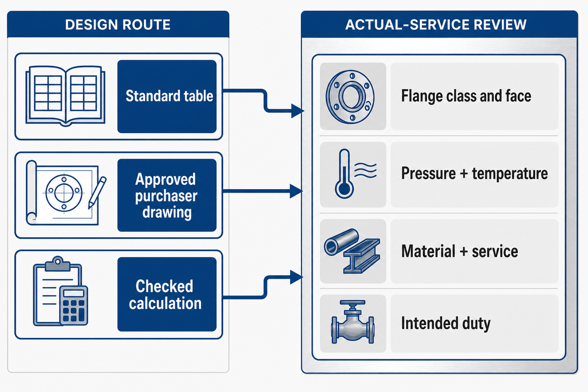
Choose paddle blind thickness and dimensions from the governing standard table, an approved purchaser drawing, or a calculation checked for the actual boundary conditions. The decision must combine size, flange class and face type, material, design pressure and temperature, corrosion allowance where applicable, and duty. Pipe schedule alone does not define a line blank.
Mechanically the plate spans the flange bore, providing resistance to the differential pressure, but its edges and sealing surfaces must fit a defined joint. Altering the unsupported diameter, material strength at temperature, facing, or duty can alter the required design even when the connected pipe carries the same schedule identifier.
Why a generic thickness chart is risky
Internet charts often omit the standard edition, flange family, material assumptions, corrosion allowance, or whether the values are for an operational line blank, a stocked product, or a temporary test tool. Precise-looking values can still answer the wrong question. Use a chart only when its controlled source and applicability match the project.
Face and material selection
Match the specified flange-facing system and its approved sealing arrangement. Flat-face, raised-face, and ring-type-joint (RTJ) configurations are not interchangeable labels. Material selection must also reflect the service fluid, design temperature, corrosion mechanism, cleaning requirements, and traceability standard; high-temperature service requires the rating and material basis to be checked at the actual temperature. Buyers considering forged carbon steel, stainless steel, or another alloy still need the component-specific material and duty stated in the order documents; the site’s ASTM A105 material overview is context, not approval.
Treat pressure and temperature as a pair. Treat pressure class as a rating designation tied to the applicable material and standard, not as a single pressure number that can be copied across services.
Slip Blind vs Blind Flange vs Spectacle Blind vs Spacer
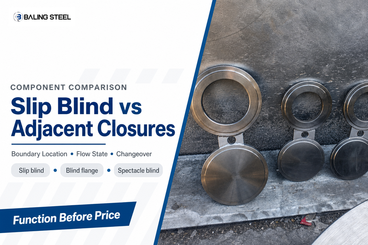
Use a slip blind for a removable solid barrier within a flanged line, a blind flange for a bolted end closure, a spectacle blind for a linked open-and-closed pair, and a spacer for the open position of a paddle-blind pair. Factors influencing choice include piping function, changeover frequency, available space, and approved isolation philosophy.
Isolation Component Choice Ladder
The Isolation Component Choice Ladder selects hardware by function before material or price enters the discussion. Start with the question “Where must the pressure boundary sit?” Then check how the line returns to service and how the installed state will be identified.
- Slip blind or spectacle blind
- Barrier sits inside the flanged joint
- Open condition needs a spacer or spectacle-blind rotation
- State identification must be planned
- Blind flange
- Closure bolts to a pipe end or nozzle
- Has its own bolt-hole pattern
- Removal opens the terminal connection
| Decision factor | Slip blind | Blind flange | Spectacle blind | Spacer |
|---|---|---|---|---|
| Boundary location | Between mating flanges | Pipe end or nozzle | Between mating flanges | Between mating flanges |
| Flow condition | Closed | Closed terminal | Selectable open or closed | Open |
| Perimeter bolt holes | No | Yes | No | No |
| Companion part | Matching open spacer | Not normally paired as a set | Open and closed sides are connected | Matching solid blind |
| Visible state cue | Solid handle or project marking | Installed flange body | Position of connected pair | Open handle or project marking |
| Envelope need | Handle clearance | Bolt and tool access | Clearance for the connected pair | Handle clearance |
| Changeover logic | Exchange with spacer | Remove or reinstall closure | Reposition the connected assembly | Exchange with solid blind |
| Specification basis | Line-blank standard or drawing | Flange standard or drawing | Line-blank standard or drawing | Matched line-blank basis |
| Not suitable when | A terminal bolted closure is required | A removable internal barrier is specified | Available clearance cannot accept the pair | A closed pressure barrier is required |
For terminal-closure geometry and sourcing, use Baling Steel’s blind flange product and specification page. For a wider view of flange categories, the flange type guide helps separate end closures from welded and joint-specific flanges.
Where Slip Blinds Are Used
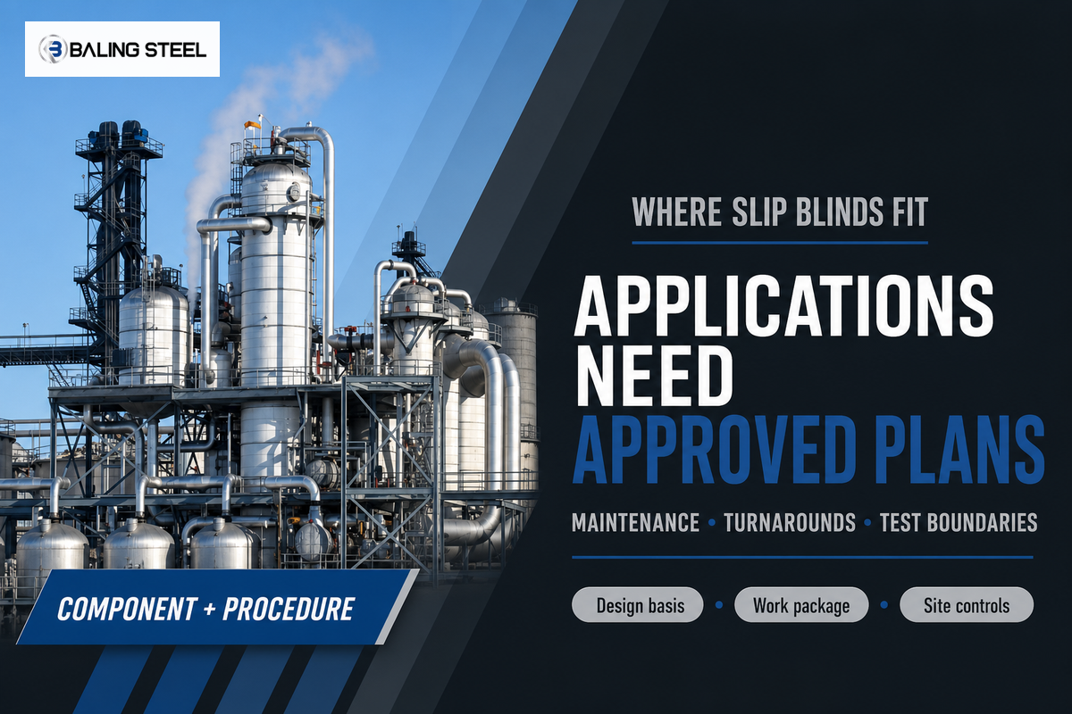
Slip blinds are used where an approved piping plan calls for a visible, removable physical barrier or positive isolation point. Common settings include maintenance isolation, refinery, petrochemical and chemical processing turnarounds, modification work, temporary process segmentation, and some pressure-test boundaries. Every application still needs a design basis, an approved work package, and site-specific energy isolation.
During a planned turnaround, a project may need a high-pressure piping system physically separated from an active process area while equipment is opened or modified. At a designated flange pair, this component can provide the specified barrier. Work teams must still control residual pressure, temperature, trapped material, backflow paths, and reaccumulation under the facility’s approved procedure.
For pressure testing, do not assume that a maintenance-isolation blind is automatically adequate. Test pressure, test temperature, fluid, duration, boundary restraint, gasket arrangement, and the approved test package all matter. Drawings or calculations should state the test duty explicitly.
Baling Steel’s public project portfolio includes oil and gas, petrochemical, pipeline, offshore, and water-treatment segments. The projects published therein provide useful supplier context, but they do not offer proof that a particular slip blind was delivered to a specific named project or fulfilled a particular specified order requirement.
Safety Boundary: A Component Is Not an Energy-Control Procedure
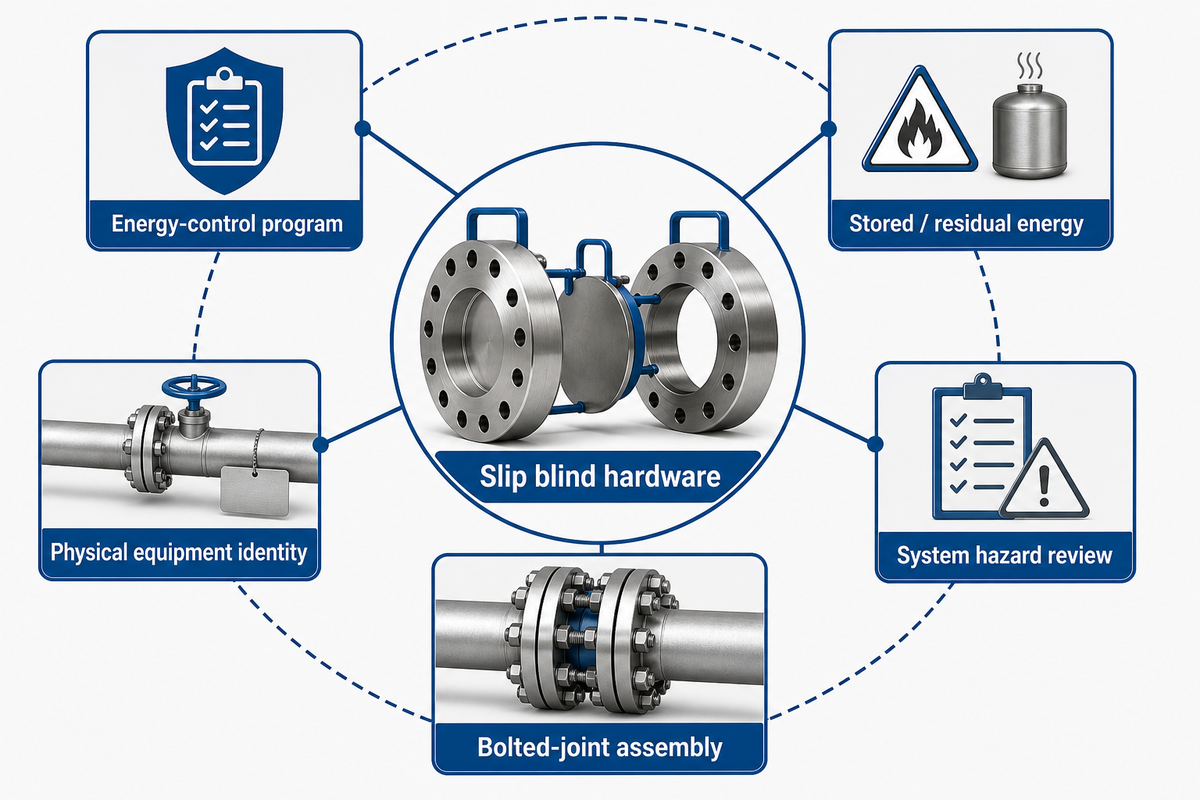
A bolted slip blind can be one physical element in hazardous-energy control, but it doesn’t by itself make equipment safe to service. Under the applicable US framework, the employer’s program must address energy-isolating devices, stored or residual energy, and verification. Jurisdiction, process hazards, and the approved site procedure determine the actual work controls.
OSHA’s control-of-hazardous-energy standard explicitly includes blank flanges and bolted slip blinds in its definition of lockout devices. That standard also requires a program and procedures intended to prevent unexpected energization or the release of stored energy. Hardware and procedure are therefore related, but they aren’t the same thing.
This OSHA citation is a United States servicing-and-maintenance boundary, not a universal process-isolation rule. The employer, facility, task, equipment, and jurisdiction determine the applicable legal and procedural requirements; the component guide can’t decide that scope.
Permit-required confined-space work has a different US regulatory boundary. OSHA’s 29 CFR 1910.146 separately defines blanking or blinding as complete-bore closure by a solid plate capable of withstanding maximum line pressure without leakage beyond the plate. That definition belongs to the permit-space rule; it shouldn’t be transferred to every process-isolation task or used as a universal purchase specification.
“the absolute closure of a pipe, line, or duct by the fastening of a solid plate”
OSHA’s energy-control guidance distinguishes a physical isolation barrier from control circuitry and emphasizes rendering stored or residual energy safe and verifying isolation before servicing. UK HSE’s safe-isolation guidance HSG253 likewise treats valves, spades, and blank flanges as parts of a wider isolation system.
This guide doesn’t prescribe line breaking, depressurization, draining, purging, gas testing, permits, personal protective equipment, or bolt-removal steps. Competent organizations must define those controls for the actual process and jurisdiction.
System effects also matter. HSE’s pipework design guidance notes that maintenance isolation standards and trapped-liquid thermal expansion require attention. Line drawings, hazard reviews, and approved isolation plans must consider alternate energy and material paths beyond the two visible flanges.
Documents don’t replace positive identification at the workface. In its 2026 PEMEX Deer Park investigation report, the US Chemical Safety Board found that drawings and flange lists didn’t distinguish nearly identical pipe segments before workers opened the wrong flange. An isolation plan should therefore require the responsible team to verify the physical equipment identity against the approved work scope; this guide doesn’t prescribe the site’s verification method.
Joint integrity is another separate evidence domain. The public ASME PCC-1-2022 scope covers pressure-boundary bolted flange joint assembly, assembler qualification, and troubleshooting leak-tight performance. A line blank that matches its component specification doesn’t by itself prove correct gasket selection, bolting practice, qualified assembly, or a leak-tight remade joint.
Seven Common Specification and Procurement Errors
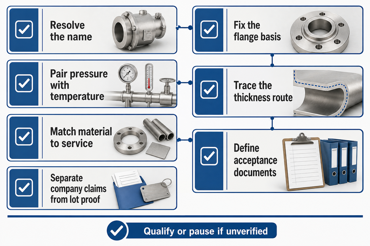
Many preventable purchasing errors are visible before manufacturing: the wrong component name, an incomplete flange basis, or an unsupported thickness copied from another job. The current ASME B16.48 scope separates ratings, materials, dimensions, tolerances, marking, and testing, which is why one catalog field can’t replace the purchase basis. These seven checks convert recurring gaps into document questions. If a field can’t be verified, qualify the quotation or pause the order rather than replacing missing evidence with a confident assumption.
- Resolve the name — state whether the order needs a solid paddle blind, an open spacer, a spectacle blind, or a blind flange.
- Fix the flange basis — record the mating standard, class, size, series where relevant, and face.
- Pair pressure with temperature — never treat class as one universal pressure value.
- Trace the thickness route — identify the standard table, approved drawing, or calculation.
- Match material to service — include grade, fluid, temperature, corrosion, and cleaning constraints.
- Define acceptance documents — drawing, material records, inspection plan, marking, and deviations belong in the RFQ.
- Separate company claims from lot proof — request order-specific traceability and release evidence.
A broad blind flange guide can help explain terminal closures, while a carbon-steel blind flange guide adds material context. Neither type of page should be used as a substitute for the line-blank drawing and acceptance package.
Slip Blind RFQ Checklist
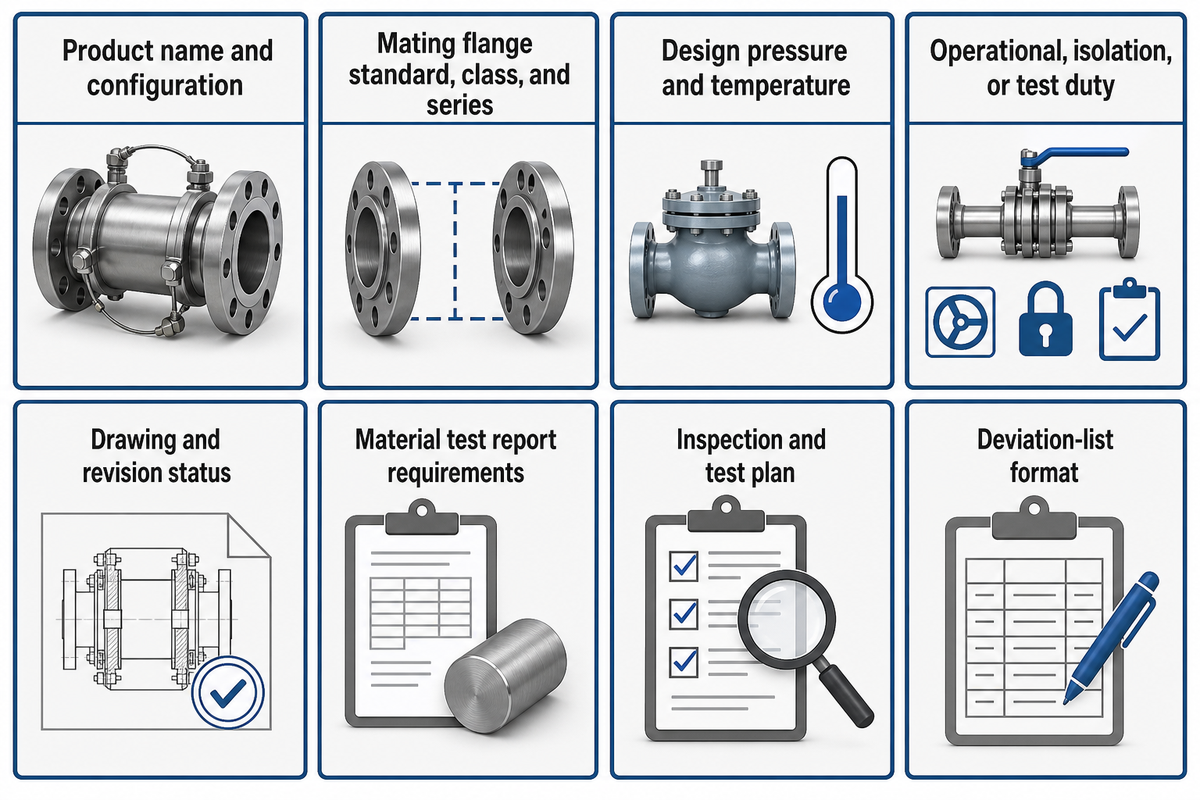
A useful RFQ tells the supplier what must fit, what service it must withstand, what evidence will be reviewed, and how deviations will be handled. Use the following checklist as a scoping template, then attach the relevant piping or component drawing. Inspection and documentation depth should match service risk, component criticality, the governing line-blank specification basis, and the project quality plan; not every order needs the same document set. Resolve fields that affect fit, duty, acceptance, or bid comparison before technical evaluation.
RFQ Fields to Resolve Before Quotation
Resolve these 12 engineering inputs and 6 commercial controls before bids are compared.
- Product name and configuration
- Standard and edition
- NPS or DN
- Mating flange standard, class, and series
- Facing and finish
- Material grade and material standard
- Design pressure and temperature
- Service fluid and corrosion constraints
- Operational, isolation, or test duty
- Thickness and dimension basis
- Marking and traceability
- Drawing and revision status
- Material test report requirements
- Inspection and test plan
- Deviation-list format
- Packing and preservation
- Quantity and spares
- Required delivery date and destination
Ask bidders to list every deviation against the inquiry rather than burying exceptions in a general quotation. Technical evaluation should compare the same standard edition, duty, material, inspection scope, and document package. Lower pricing based on omitted testing or a different thickness route is not a like-for-like bid.
How to Evaluate a Supplier Without Overreading Marketing Claims
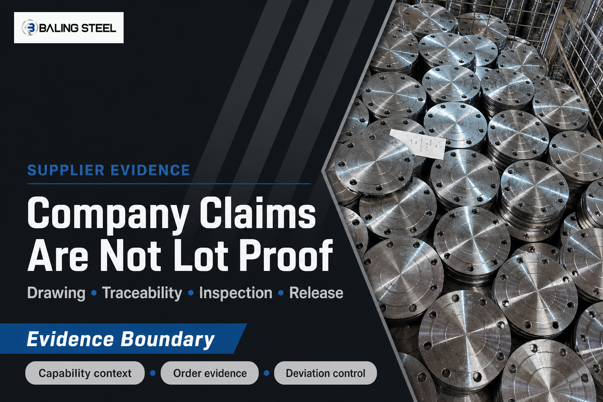
Evaluate a supplier in layers: public company identity, relevant product scope, quality resources, quotation-specific engineering, and order-specific evidence. Public identity, product scope, and quality resources help qualify a vendor; quotation engineering and order evidence decide whether a particular slip blind meets the purchase requirement. Company certificates can’t stand in for a drawing, traceable material record, or release note.
Baling Steel states on its quality and capability page that it has more than 25 years of steel-industry experience and operates an independent laboratory for chemical, mechanical, impact, and related testing. Its company profile provides the public identity behind the brand. These are attributed supplier statements, not acceptance criteria or test results for a particular production lot. Ask for the order-specific drawing, material traceability, inspection plan, test records, marking, and final document index that apply to the quoted item.
Decision Framework: Which Isolation Component Should You Specify?
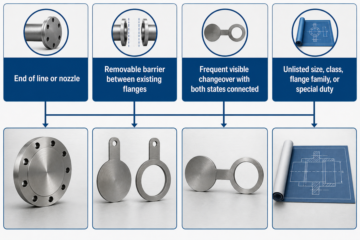
Specify the component by boundary location and changeover need. Choose a blind flange for a terminal end closure, a slip blind with spacer for a removable between-flange barrier, or a spectacle blind when the connected open-and-closed pair suits the approved layout. Outside the cited standard scope, route the item to engineered purchaser documentation.
- End of line or nozzle: evaluate a blind flange.
- Removable barrier between existing flanges: evaluate a solid paddle blind and matching spacer.
- Frequent visible changeover with both states connected: evaluate a spectacle blind.
- Unlisted size, class, flange family, or special duty: issue an engineered drawing and purchaser specification.
A practical commercial safeguard is to lock the flange interface, isolation state, duty, and acceptance evidence before quotations are compared.
Send a specification-ready inquiry
Provide the 12 Line-Blank Interface Lock fields, required documents, quantity, and delivery date. Baling Steel can then review the inquiry against its available manufacturing and supply scope without converting missing fields into assumptions.
Frequently Asked Questions
What is a slip blind?
A slip blind is a removable solid line blank placed between two mating pipe flanges to block the flow path and create a visible physical isolation point.
How do I select the right slip blind thickness?
Select thickness from the governing standard, approved purchaser drawing, or checked engineering calculation that matches the actual service, material, pressure, temperature, flange arrangement, and intended duty.
What is the difference between a slip blind and a blind flange?
A slip blind sits inside a flanged joint as a removable barrier, while a blind flange uses its own bolt holes to close a pipe end, outlet, or nozzle.
Is a paddle blind the same as a slip blind?
Paddle blind, spade, line blank, pancake blind, and slip blind often describe the same solid handled component used between mating pipe flanges under project-specific terminology.
Can a slip blind be used for hydrostatic testing?
A slip blind can serve as a hydrostatic-test boundary only when the approved design and test package explicitly verify the component, flange arrangement, pressure, and temperature.
Evidence Boundary for This Guide
This article combines public ASME scope information, regulator guidance, search-intent evidence, and Baling Steel’s published company pages. It doesn’t reproduce licensed standard tables or claim that a particular product lot is certified.
Related Articles
- Blind flange fundamentals and end-closure selection
- Common flange types and where they fit
- Slip-on flange guide: a different component
- Carbon steel blind flange material guide
References & Sources
- ASME B16.48-2025: Line Blanks The American Society of Mechanical Engineers
- ASME B16.5-2025: Pipe Flanges and Flanged Fittings The American Society of Mechanical Engineers
- 29 CFR 1910.147, Control of Hazardous Energy US Occupational Safety and Health Administration
- 29 CFR 1910.146, Permit-Required Confined Spaces US Occupational Safety and Health Administration
- Energy Control and Verification Guidance US Occupational Safety and Health Administration
- HSG253: The Safe Isolation of Plant and Equipment UK Health and Safety Executive
- Design Codes: Pipework UK Health and Safety Executive
- ASME PCC-1-2022: Pressure Boundary Bolted Flange Joint Assembly The American Society of Mechanical Engineers
- PEMEX Deer Park Refinery Investigation Report US Chemical Safety and Hazard Investigation Board