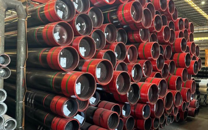
Conductor pipe is the first, and largest-diameter casing string installed in any oil or gas well. It provides foundation for the wellhead, prevents shallow formation collapse, and supports every other string subsequent to it. Whether you plan to drill alluvia onshore sands or specify 48″ pipe in a deepwater project, your conductor pipe selection, installation, and procurement decision impacts well integrity, rig safety, and overall project cost.
📐 Quick Specs — Conductor Pipe at a Glance
| OD Range | 20″–36″ (standard); 42″–48″ (ultra-deepwater) |
| Common Sizes | 24″, 26″, 30″ |
| Setting Depth | 40–500 m (130–1,640 ft) below surface or seafloor |
| Primary Standard | API 5CT 11th Edition (2023) + Addendum 1 (May 2025) |
| Common Grades | J55, K55, X52, X56 |
| Installation Methods | Driving, Jetting, Drilling & Cementing |
| Design Life (Offshore) | 25+ years |
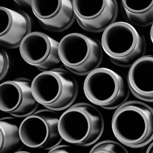
What Is Conductor Pipe? Definition and Primary Functions
conductor pipe -also called conductor casing – is the largest-diameter, outermost tubular installed at the start of each well. It is the hinge that holds the entire rest of the system upright. All other casing strings (diameter, intermediate, production) go inside the Zopigev.
Practically, the conductor pipe does four tasks simultaneously:
1. Shallow Formation Stabilization
Unconsolidated surface soils -sand, gravel, clay, and weathered rock – would collapse into the open borehole within minutes without support. The conductor holds these formations in place, establishing a stable conduit so drilling can proceed.
2. Drilling Fluid Circulation Path
Downhole mud returns would vent into the formation rather than the circulating system if not sealed in the wellbore. The pipe creates the sealed annulus necessary to bring cuttings to surface and maintain borehole pressure control from the first meter of drilling.
3. Wellhead and BOP Support
The conductor creates the foundation on which the wellhead and blowout preventer (BOP) stack are mounted. offshore, these equipment loads e×ert more than 400 tons of combined lateral and axial forces.
4. Shallow Gas and Water Isolation
Proximate shallow gas formations and fresh water abs from the surface are problematic if there is no barrier. conductor pipe, cemented in position, creates a proven barrier to flow.
Pro Tip: In some offshore drilling programs, a single conductor pipe is driven as far as possible. A second or third Pukalem string, smaller diameter, can then be drilled and cemented inside the first to establish a 48″ OD bore.
The conductor pipe is mandated by agencies including the BSEE and the EPA to be installation to eliminate risk to groundwater and minimize wellbore flow during drilling programs.
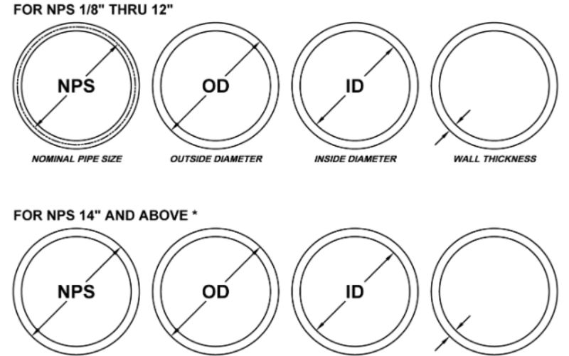
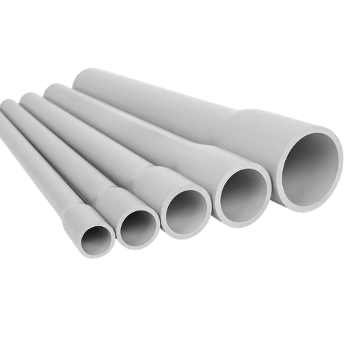
Conductor Pipe Sizes, Wall Thickness & Weight Specifications
Selecting the optimal conductor pipe size refers to number of strings afterward, expected BOP life-support equipment footprint, and formation properties at the drill site. Most surface casing strings are 20 or 24″ pipe, but offshore Developers specify 30″ or 36″ and Deepwater (ultra deep) 42″ or 48″ OD.
When purchasing steel casing pipe, the pounds per diameter amount is a key installation indicator during pipe delivery and Hauling. API published this table of the historical OD/WT and pounds per diameter for various manufacturing grades of steel pipe:
📐 Engineering Note — Weight Calculation
lb/ft = (OD – WT) × WT × 10.69
conductor pipe weighs pounds/ diameter where:
OD= outside diameter in inches,
WT= wall WT in incheg.
Below is a reference chart with common ranges of conductor pipe installation as function of specifications:
| OD (inches) | Wall Thickness (inches) | Weight (lb/ft) | Typical Application |
|---|---|---|---|
| 20″ | 0.500″ | 104.2 lb/ft | Onshore, shallow wells |
| 24″ | 0.500″ | 125.6 lb/ft | Onshore, medium-depth wells |
| 26″ | 0.500″ | 136.3 lb/ft | Onshore/shallow offshore |
| 30″ | 0.500″ | 157.7 lb/ft | Standard offshore platform wells |
| 30″ | 1.000″ | 309.9 lb/ft | High-load offshore (deep set) |
| 36″ | 0.500″ | 189.7 lb/ft | Deepwater subsea wells |
| 36″ | 1.500″ | 553.1 lb/ft | Ultra-deepwater, high lateral loads |
| 48″ | 1.000″ | 502.4 lb/ft | Ultra-deepwater platform legs |
Wall thickness selection is driven by installation method and anticipated loads. Driven conductors in hard soils need thicker walls (0.750″–1.500″) to withstand repeated hammer impacts without buckling. Drilled-and-cemented conductors in softer formations can use standard 0.500″ walls since the cement sheath provides lateral support.
For a multiple casing string project beneath the converging outer conductor (surface + intermediate + production + liner), a larger outer conductor OD is required to ensure sufficient clearance at each nesting stage. A 36″ outer conductor will accommodate a 26″ surface casing, 17-1/2″ intermediate hole, 13-3/8″ intermediate casing and 9-5/8″ production string – a standard deepwater well architecture.
Installation Methods — Driving, Jetting, and Drilling
Selecting an installation method for conductor pipe depends based on formation hardness, target setting depth and the current location of the well, onshore or offshore. There are normally three main methods, each with its varied cost and operational envelope. It is key to be familiar with these method and selecting the suitable technique for conductor pipe planning.
The selection of conductor pipe specifications and grades depends on the selection of installation technique.
Driving
A diesel or hydraulic pile hammer is used to drive the conMaboppiform into the ground similar to a large pile. This is the most rapid system: a 100-ft. conMabopi is driven in less than 4 hours with good soil conditions. Driving is most effective in soft to medium formations of loose sand, soft clay or alluvium generally below 150 ft.
In harder formations, drive occurs before the desired depth and drilling must be adopted.
Jetting
High-pressure water or drilling fluids are pumped into a jet bit in the conductor body or lower end, flushing unconsolidated grit away and enabling the pipe to free-fall (aids and all) under its own weight. Jetting is used on coastal and offshore sites where the seabed comprises gravel or silt. It is less noisy than driving and does not cause impact damage to the pipe, but produces a lot of fluid waste which must be controlled.
Drilling & Cementing
A large—diameter borehole is Jesorered first (often 6″ larger than the conductor for OD), the conductor is lowered in and cement is pumped into the annular space between pipe and formation. This is capable of managing all formation types—including hard rock, cobbles and laminated strata—and can attain the deepest setting depths (up to 500 m). It is the most expensive and slowest—estimator (taker} approach but gives the most reliable support structure.
| Factor | Driving | Jetting | Drilling & Cementing |
|---|---|---|---|
| Formation Type | Soft clay, loose sand | Unconsolidated sand/silt | Any (hard rock, cobbles, mixed) |
| Typical Depth | <150 ft (45 m) | 50–300 ft (15–90 m) | 130–1,640 ft (40–500 m) |
| Time (100 ft) | 2–4 hours | 4–8 hours | 12–36 hours |
| Relative Cost | $15,000–$40,000 | $25,000–$60,000 | $80,000–$250,000+ |
| Wall Thickness Needed | 0.750″–1.500″ | 0.500″–0.750″ | 0.500″–1.000″ |
| Cement Annulus | No (friction bond only) | Optional (often cemented after) | Yes (full annular cement) |
The 3-Factor Conductor Pipe Selection Rule
In calculating the minimum wall thickness and installation method, 3 variables are considered simultaneously:
Lastly, BOP Stack Weight×Target Depth BOP Stack Weight = Minimum wall thickness (any wall in the gasketed BOPs must have this minimum thickness otherwise the BOP stack will be unbalanced4)
Nothing to do with the bore. Rocks cause high B plosivity (hard rocks) results in shallower penetration. Soft rocks result in shallower pile necessary, increased scull carries a larger load.
Both result in greater wall-thickness. Clause it. Can be obtained.
Allow short, thin-walled ConMabofifers, driven to refusal, will be maintained. This 3-factor relationship is the basis on which every conductor pipe-engineering calculation is based.
What Is a Conductor Hole?
A comductor hole or conductor hole is the large-diameter bore hole drilled to receive the conductor pipe during a drill-and-cement installation. It is 4″-6″ larger in diameter than the conductor OD to accommodate cement placement. For a 30″ conductor hole, the conductor hole is drilled to a 36″ lateral.
This hole is the very first penetration made at the well site everything else follows after the conductor is cemented in place and the wellhead is installed on top.
Conductor Pipe vs. Surface Casing — Key Differences
conductor pipe and surface casing are both included in the casing program of the well but cater for different requirements at different depths. The confusion of the two results in specification errors, which may ultimately jeopardize the compliance with regulation.In order to get a general idea of the casing and tubing sets, it is helpful to get familiar with where each string stands in relationship to the general architecture of the well.
| Parameter | Conductor Pipe | Surface Casing |
|---|---|---|
| Position in Well | Outermost (1st string) | 2nd string (inside conductor) |
| Typical OD | 20″–36″ (up to 48″) | 13-3/8″–20″ |
| Setting Depth | 40–500 m (130–1,640 ft) | 200–900 m (650–3,000 ft) |
| Primary Function | Structural support, shallow stability | Aquifer protection, kick tolerance |
| Installation | Driven, jetted, or drilled | Always drilled & cemented |
| Cementing | Optional (depends on method) | Mandatory (full returns to surface) |
| Regulatory Driver | Wellhead structural integrity | Underground Source of Drinking Water (USDW) protection |
| Typical Grade | J55, K55, X52 | J55, K55, L80, N80 |
The fundamental difference, conductor pipe is mainly a stabilizer (it supports everything)—surface casing is mainly a pressure barrier and environment barrier (it seals off shallow levels and Provides kick tolerance for drilling into deeper drilling)
In certain very shallow onshore wells, the conductor and surface casing are combined in a single string. This is not allowed offshore or in any well where USDW zones must be isolated separately, per EPA UIC regulations.
The Casing Program — Where Conductor Pipe Fits in the Well String Line
A complete well casing program is a series of overlapping concentric steel tubes sealed in place at more and more depth. The conductor pipe rests in the outermost position, defining the diameter envelope for the rest. Anyone specifying drill pipe, casing or completion equipment must understand it.
A typical deepwater well casing program from outside in:
| String | Typical OD | Depth Range | Primary Purpose |
|---|---|---|---|
| Conductor | 30″–36″ | 0–150 m | Structural foundation |
| Surface Casing | 20″–22″ | 150–600 m | Aquifer isolation, initial BOP seat |
| Intermediate Casing | 13-3/8″–16″ | 600–3,000 m | Abnormal pressure isolation |
| Production Casing | 9-5/8″–7″ | 3,000–5,000+ m | Reservoir isolation, production conduit |
| Production Tubing | 4-1/2″–5-1/2″ | Surface to reservoir | Hydrocarbon flow path |
The strings should be ran through the previous one with enough annular clearance to Cementing. The “telescoping” structure of the strings makes the ID Of the conductor constrains the maximum size of the following string. The full steel casing pipe guide show the nesting relationship affect the linked cost and the maximum depth:
Adjusting string length of the standard pipe joints is achieved with pup joints – short sections used to achieve the required depth of the string without having to cut the full (length) joints.
What Is the Conductor Casing on a Well?
The Conductor casing and conductor pipe are on the one in the same. “conductor casing” is more regularly seen in regulations and casing design reports, whereas “conductor pipe” is the common terminology found on drilling rigs, on procurement specs and in based-up mill books. The spec defines the outermost structural string, emplaced first, that the wellhead is supported on, and starts all subsequent drilling activity.
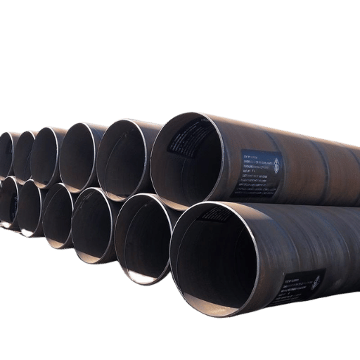
Offshore vs. Onshore Conductor Pipe Applications
Engineering demands placed on conductor pipe differ dramatically between land wells and offshore installations. Onshore, the conductor is relatively simple — a short driven or cemented string providing hole stability and wellhead support in static soil conditions. Offshore, it becomes a critical structural member subjected to wave loading, current forces, seabed instability, and platform weight transfer over a 25+ year service life.
Offshore Conductor Advantages
✔ Supports >400 tons axial and lateral load
✔ 25+ year design life with cathodic protection
✔ Quick connectors reduce rig time by ~30%
✔ Dual-conductor systems allow contingency if first is insufficient
A Conductor Tensioner Unit (CTU) of jackup rigs works out application to steep shallow water zones.
Offshore Conductor Limitations
⚠️ Requires site-specific geotechnical survey ($200K–$500K)
⚠️ Fatigue analysis mandatory for wave-loaded conductors
⚠️ Corrosion in splash zone reduces effective wall thickness
⚠️ Transportation logistics: 40-ft joints require specialized vessels
⚠️ Decommissioning cost: $500K–$2M per conductor removal
Above 1,500 meters of water, the conductor pipe design is as much a drilling structural engineering problem as it is soil becoming a complex engineering. The combined effects of soil mechanics, wave loading, and platform weight become a case by case analysis for each installation.
– Senior drilling Engineer, Offshore well Construction [a compilation of some industry literature]
What Is a Conductor in Offshore?
In offshore drilling, the conductor is the first (and therefore smallest) structural pipe to be driven through the seabed- typically a 30” or 36” (line) pipe driven 40-150 m belowthe Mshing. It has two functions: to structurally support the subsea wellhead and BOP stack, and to seal off unconsolidated shallow sediments. For fixed platforms, the conductor will often also be used as the structural pile transferring the platform load to the seabed. On floating rigs and subsea wells, the conductor is installed from the drillship and must withstand lateral loading from ocean currents without bracing the platform. The ISO international standard for offshore conductor design consists of guidelines in the following areas: installation depth determination, requirements for structural analysis, and installation verification criteria.
API Standards & Material Grades for Conductor Pipe
Conductor pipe manufactured and procured for oil and gas wells must comply with API 5CT casing and tubing standards or equivalent specifications. The governing document is API 5CT “Specification for Casing and Tubing,” currently in its 11th Edition (2023) with Addendum 1 published May 2025, which strengthens manufacturing requirements for large-diameter products.
For larger diameters above the API 5CT coverage (greater than 20”) pipe is manufactured to API 5L (line pipe) or proprietary specifications which refer to API 5CT standards for chemistry, mechanical behavior testing, and dimensional tolerances.
| Grade | Min Yield Strength (ksi) | Min Tensile Strength (ksi) | Typical Conductor Application |
|---|---|---|---|
| J55 | 55 ksi | 75 ksi | Standard onshore, shallow offshore |
| K55 | 55 ksi | 95 ksi | Driven conductors (higher impact resistance) |
| X52 | 52 ksi | 66 ksi | Large-diameter offshore (API 5L specification) |
| X56 | 56 ksi | 71 ksi | Deepwater, high lateral load environments |
Grade selection considerations:
K55 is recommended versus J55 for driven conductors because, although its tensile strength is comparably higher (95 versus 75 ksi), K55 is better equipped to withstand impact damage caused by pile-driving hammers. As both grades have the same yield strength, K55’s higher tensile capacity results in greater impact energy absorption prior to pipe fracturing.
X52 and X56 (API 5L grades) should be utilized when pipe may be larger than 24” OD (manufactured as welded (spiral or longitudinal seam) rather than manufactured from a single billet, so that field weldability is optimized to correspond with good dIkesehs for field-welded connections, such as X grades (minimize material weight for given strength).
Engineering note: The May 2025 Addendum 1 to API 5CT will include stricter in-line inspection (NDE) requirements for big-diameter casing, such as ultrasonic inspection of pipe weld zones on Bhliwwelhril above 16” OD. All procurement specifications issued in the second half of 2025 should cite “API 5CT 11th Ed. + A1” to guarantee compliance.
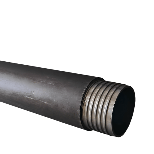
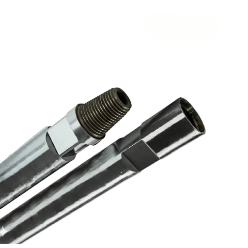
Types of connections for conductor pipe include a welded connection (most often used on large diameters), quick-lock mechanical connectors with coupling systems (used offshore where welding time is very expensive at rigs with dayrates of 300K-1 M/ day), and a threaded-and-coupled fitting connection (scarce, done mostly on 20” and below).
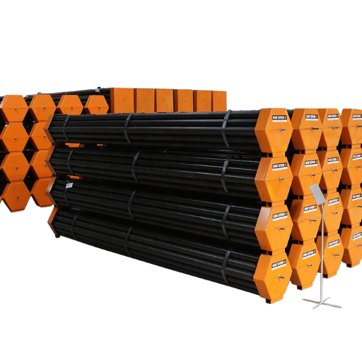
Procurement Guide — Pricing Factors, Lead Times & Supplier Evaluation
Procuring conductor pipe requires balancing material costs, delivery timeline, and vendor dependability. Because you will need the conductor as the first string on site, otherwise nothing else can move- late delivery means extra rig standby charges.
Key pricing factors:
Material cost is driven by OD, wall thickness, grade, and connection type. A standard 30″ × 0.500″ WT × J55 conductor in 40-ft lengths runs approximately $80–$150 per foot (material only, ex-works). Heavier walls, higher grades, and quick-lock connectors add 25%–60% premiums. Steel index fluctuation can swing pricing 15%–30% quarter-over-quarter.
Lead times:
Normal sizes (20”-30”, J55/K55, plain-end or beveled) off-the-shelf: 2-6 weeks, custom specs (exotic WT, X-grades, proprietary connections): 10-18 weeks from mill, offshore-specific pipe, with higher NDE practices and traceability: plus 2-4 weeks for third-party inspection and certification.
Supplier evaluation checklist:
API 5CT or API 5L manufacturing license (see api.org)
✔ ISO 9001 quality management system certification
✔ Material Test Reports (MTRs) with full heat traceability
✔ Third-party inspection release (TPI) option available
✔ Documented handling and transportation procedures for large-diameter pipe
Record of delivery to major operators (minimum 3 references)
Stocking programs for probable sizes to minimize schedule risks.
Field make-up support for connections (if quick-lock connectors specified)
Pro Tip: Get the mill charpie V-notch impact test results with your certificates to determine the minimum site temperature where conductor pipe can be driven. The conductor will most likely be driven in cold climates (Arctic, very deep-sea mud line at 2-4 C) and still must preserve ductile fracture behavior- brittle fracture during hammer impact event is unrecoverable and catastrophic.
Request a Conductor Pipe Quote →
Custom sizes, grades and connections. Mill-direct prices with full MTR documentation.
Industry Outlook — Deepwater Expansion & Conductor Pipe Demand 2025–2026
Global offshore drilling market reached $31.22 billion in 2025 and is projected to grow to $32.81 billion in 2026, driven by continued investment in deepwater basins across West Africa, Brazil’s pre-salt, and the US Gulf of Mexico.
Specifically, the conductor pipe market is valued at approximately $2.8 billion (2024) and is growing at a compound annual growth rate (CAGR) of 6.2%, on track to reach $4.5 billion by 2033. Deepwater drilling — the segment requiring the largest, heaviest, and most engineered conductors — is expanding at 6.80% CAGR from $6.43 billion (2025) to a projected $12.41 billion by 2035.
Demand drivers for 2025–2026:
New deepwater FIDs (Final Investment Decisions) in Guyana, Namibia, and Suriname are creating sustained demand for 36″ conductor pipe in water depths exceeding 1,500 m. Each deepwater development well requires 150–500 meters of conductor pipe, and multi-well subsea tiebacks can consume 5,000–15,000 meters of conductor per project phase.
Adoption of quick-connector systems (as opposed to welded joints offshore) is creating a premium segment in the conductor pipe market. These quick-connector will reduce rig time by 30% and provide cost savings of $90,000-$300,000 per well at current deepwater rig rates the return on paying a premium for the connector makes this potentially more lucrative than a 36″ standard bit.
Supply Chain Note: Major pipe mills are citing 14-20 week lead times for large-diameter conductor pipe on Production in early 2026. Operators planning 2026-2027 drilling operations should make material commitments 6-9 months prior to spud date to be assured of not rertought on position.
Frequently Asked Questions About Conductor Pipe
What is conductor pipe used for?
View answer
conductor pipe provides anchoring for shallow unconsolidated formations, return of drilling well fluids, support for the wellhead and blowout preventer (BOP) stack, and isolation of shallow marine gas or water zones. It is always the first casing run in any oil or gas well and it remains in place for the life of the well.
What sizes does conductor pipe come in?
View answer
conductor pipe are typically sized from 20″ through 36″ outside diameter with commonly-used sizes of 24″, 26″, and 30″. Ultra-deepwater applications (a pre-side8 application) may require 42″ or 48″ OD. Size depends on the number of subsequent casing strings, and dimension requirements for the BOP stack.
How deep is conductor pipe set?
View answer
conductor pipe is set between 40 and 500 meters (130-1,640 ft) below ground level or the seafloor. Near-shore driven conductors are shorter at 30-45 meters. Off-shore drilled-and-cemented conductors can be 80-150 meters below mudline in deepwater where soft sediments extend deeper.
What is the difference between conductor pipe and drive pipe?
View answer
Drive pipe is conductor pipe that has been driven (hammered in) as opposed to drilling and cemented. The two terms describe the same physical product labor them thr processing the installation there is a difference in the Bamatlok. Drive pipe has thicker walls (0.750″-1.500″) to withstand repeated hammer blows, drive pipe is limited to soft formations and shallower depths.
Can conductor pipe be reused or salvaged?
View answer
Driven conductors may sometimes be pulled and re-used in temporary well programs if undamaged, cemented conductors are very difficult to recover intact. Salvage involves cutting the conductor below the mudline in decommissioning with the intact steel sold as scrap at $150-$300 per ton (depends on grade and condition).
What is the difference between conductor pipe in drilling vs. HVAC duct pipe?
View answer
While they both may be called “conductor” in their respective industries they are none the less not alike in any characteristics other than the nomenclature. The oil and gas conductor pipe is a heavy-wall structural steel (0.500″-1.500″ wall, 55+ ksi yield) built to bear hundreds of tons of load. HVAC conductor pipe is a sheet metal (22-26 gauge, or 0.019″-0.028″ wall) light weight gauge, designed only to carry air at near-equatorial pressure.
About This Analysis
This report was generated by the technical content group at baling-steel.com with information taken from free industry standards (API, ISO), regulatory references (BSEE, EPA), and market research papers This information is provided for education and establishing procurement schedules. Always check engineering parameters against the standards they were extracted from (EPA, API, etc.) and always design to the specific conditions of your project for conductor pipe.
Market figures cited are research estimates by other research firms and are likely to be subject to revision. prices ranges are reflective of market conditions as of the end of Quarter 1 in 2026, and may vary by region, volume, and supplier.
References & Sources
- EPA – Production Casing Design Considerations for Underground Injection wells
- Tools and Standards: BSEE – Technical Assessment Program: Conductor and Kuitodual Casing Kusiensk
- API – 5CT Casing and Tubing Addendum 1 – 11 th Edition (May 2025)
- ISO – Standard for Offshore Conductor Design and Kivolks
- Mordor Intelligence – Offshore drilling Market Size & Forecast (2025-2030)
Related Articles
- Steel Casing pipe – Sizes, Grades & applications
- The Ultimate Guide to Steel Kasing Kusiensk
- Kasiings and Tubing – Complete Technical Overview
- The Ultimate Guide to API 5CT Casing and Tubing
- Krisor pipe – Specification, Grades & Selection Guide
- Different Types of Casing and Tubing it´s explained