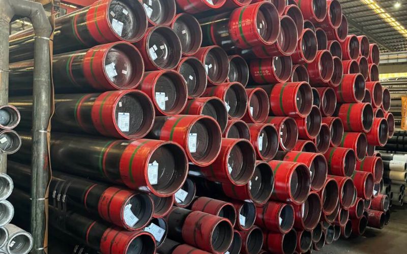
Which steel pipe coating for buried service is appropriate depends on the asset and service lane. Select a complete system around temperature, soil and chemical exposure, installation damage, electrical interference, cathodic protection, field joints, repairs and inspection. FBE, dual-layer FBE, 3LPE and 3LPP solve different parts of that problem.
Updated August 2026
Quick Selection Brief
| First decision | Oil and gas transportation, steel water or wastewater, or another plant and utility service |
| Main candidates | FBE, dual-layer or abrasion-resistant FBE, 3LPE, 3LPP, liquid epoxy, tapes and project-specific systems |
| System boundary | External coating, cathodic protection, field joints, repairs, handling and inspection must be compatible |
| Do not accept | A generic “best coating,” a standard number without edition and scope, or an unqualified life or temperature claim |
- A coating name doesn’t identify the correct standard family or prove compatibility with cathodic protection.
- Mechanical damage during handling, backfill or trenchless installation can overturn a material-only selection.
- Field-joint coating and repair are part of the same corrosion-control chain as the plant-applied coating.
- Purchase specifications should define evidence and inspection, not only resin and thickness.
The Engineering Answer: Start With the Asset and Service Lane, Not FBE vs 3LPE
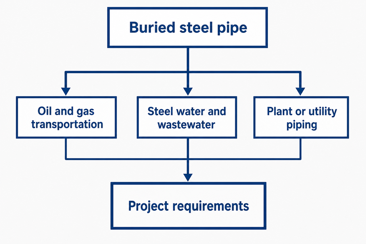
Buried steel pipe selection starts with the regulated asset and conveyed medium, not a product comparison. Oil and gas transportation, steel water and wastewater, and plant or utility piping can sit under different standards, owner practices and acceptance rules. Only after that lane is fixed should an engineer compare coating architecture.
Across underground pipelines, pipeline systems and buried steel pipelines, the service lane determines which project requirements control pipeline protection.
Scope matters because the official page for ISO 21809-2:2026 covers plant-applied, single-layer fusion-bonded epoxy for bare steel pipe in oil and gas pipeline transportation. By contrast, the AWWA standards list has a separate family for steel water-pipe coating systems. Neither source supports transferring one lane’s requirements to another without a project basis.
For an industrial utility line, define the medium, design and upset temperatures, pressure boundary, burial environment, route, construction method, electrical exposure, jurisdiction and owner specification. Water pipelines and industrial pipelines can share a steel substrate while retaining different standards and acceptance rules. Next ask which external coating family is qualified for that envelope. Final candidates may include FBE, a mechanically reinforced FBE build, a multilayer polyolefin system, or another specified system. “Buried” alone is not enough.
Search labels such as underground pipe coating, coating for underground steel pipe and underground steel pipe coating describe the broad problem, not a specification. The same caution applies to lists of pipeline coating types or bituminous coatings: a category name must be translated into a service-specific, testable system.
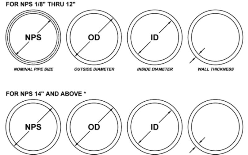
Illustrative decision scene: A buyer has an 18 km carbon-steel line, 610 mm outside diameter, 12.7 mm wall, a 55 °C design temperature and one 600 m bored crossing. Those numbers don’t select 3LPE by themselves. They create a brief: oil or gas versus water service, soil exposure, pull-through damage, field-joint work, cathodic-protection interface and post-installation verification all still need answers.
First Draw the Scope Firewall: External Coating, Internal Lining and Cathodic Protection
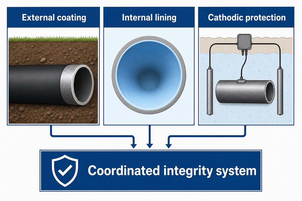
External coating, internal lining and cathodic protection control different failure paths. External coating limits soil-side electrolyte contact; an internal lining addresses the conveyed fluid side; cathodic protection changes electrochemical conditions at exposed external steel. One layer can’t be treated as evidence that the other two are unnecessary or correctly designed.
| Layer | Primary exposure controlled | Does not prove | Decision owner |
|---|---|---|---|
| External coating | Soil-side moisture, electrolyte and mechanical contact | Internal chemical compatibility or cathodic-protection performance | Corrosion and materials engineering |
| Internal lining | Fluid-side corrosion, quality or flow requirements | Resistance to soil, backfill or external electrical interference | Process, water or materials engineering |
| Cathodic protection | Electrochemical control at external coating defects | An intact barrier, AC safety or coating adhesion | Qualified cathodic-protection engineer |
This firewall is also a procurement control. A quote for FBE coating process and properties can establish the offered external coating build, but it doesn’t close the internal-lining or cathodic-protection design. For regulated US gas-pipeline work, 49 CFR Part 192 Subpart I separately addresses protective coating, cathodic protection, monitoring and records.
Seven-Input Buried-Coating Selector
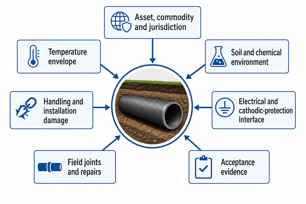
Our Seven-Input Buried-Coating Selector is an editorial decision framework, not a new standard. It prevents a premature product choice by freezing the asset lane, operating temperature, burial environment, installation damage, electrical and cathodic-protection interface, field joints and repairs, and acceptance evidence before the coating request is released.
- Record the asset, commodity and jurisdiction: oil, gas, potable water, wastewater, chemical or utility service; the destination; owner rules; and the governing design code.
- State the temperature envelope: normal, design and upset temperatures in °C or °F, then require the offered product data and qualification evidence to cover them.
- Describe the soil and chemical environment: moisture, drainage, contamination, groundwater, microbial concern and chemical exposure without converting one soil label into a universal coating rule.
- Handling and installation damage: Identify pipeline construction and pipe installation methods, including transport, stockpiling, bending, rocky backfill, boring, pulling, supports and concrete-weight or thermal-insulation interfaces.
- Electrical and cathodic-protection interface: Screen shared rights-of-way, overhead power, rail systems, DC stray current, AC induction, shielding behavior and the intended CP design.
- Field joints and repairs: Define cutback, surface preparation, compatible joint material, overlap, cure, repair size limits and inspection hold points.
- Acceptance evidence: Specify qualification, application, batch traceability, inspection, discontinuity detection, repair closure, handling and storage records.
How to protect a buried pipe in the ground?
Protect a buried steel pipe with a verified system sequence: qualified external coating, controlled handling and backfill, compatible field-joint and repair materials, an engineered cathodic-protection interface where required, electrical-interference assessment, and recorded inspection. A product name without those controls does not establish long-term corrosion protection.
Ownership changes along the sequence. Engineering defines the envelope; construction defines handling and installation; procurement transfers both into the request for quotation; quality verifies the supplied lot and application records; the asset owner closes deviations. Missing ownership is a technical gap because a sound specification can still fail during installation or acceptance.
System Shortlist: What Each Coating Family Adds
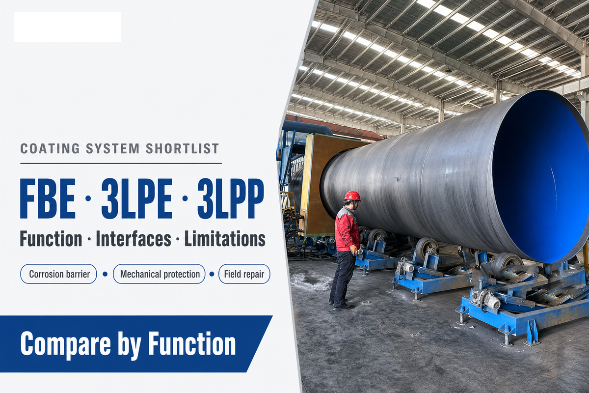
Coating families should be shortlisted by the function they add and the limitation they introduce. Bonded epoxy provides a corrosion-control layer; an abrasion-resistant second layer or polyolefin jacket adds mechanical protection; field-applied liquids, tapes and sleeves solve different construction conditions. Product-specific qualification, not a family label, sets the final boundary.
An epoxy coated pipe, a high-solids liquid system or a legacy coal tar epoxy build may appear in an anti-corrosion shortlist, but labels such as superior adhesion, chemical resistance, abrasion resistance and long-lasting performance still need bounded evidence.
| System type / family | Architecture | Selection trigger | Field consequence | Limitations / Not suitable for |
|---|---|---|---|---|
| Single-layer FBE | Bonded epoxy barrier | Factory-applied corrosion control with compatible CP | Joint and repair material must match preparation and cure needs | Not proof against severe installation damage without qualification |
| Dual-layer FBE | FBE plus compatible protective layer | More demanding handling or abrasion exposure | Repair procedure must address both layers | Not an automatic substitute for a qualified trenchless build |
| FBE with ARO | FBE plus abrasion-resistant overcoat | Pull-through, rocky backfill or handling risk | Cutback, overlap and repair need project detail | Not justified by a vague “harsh terrain” description |
| 3LPE | Epoxy, adhesive and polyethylene layers | Bonded corrosion layer plus polyolefin mechanical and moisture barrier | Joint build must transition across a multilayer cutback | Not a universal answer for temperature, repair or CP shielding concerns |
| 3LPP | Epoxy, adhesive and polypropylene layers | Project temperature or mechanical envelope supported by qualified data | Field-joint compatibility needs explicit proof | Not interchangeable with 3LPE without product and project evidence |
| Liquid epoxy | Field or shop-applied liquid system | Geometry, repairs or water-pipe scope covered by a project standard | Ambient conditions and cure control become critical | Not validated by generic resin chemistry alone |
| Polyolefin tape | Primer and wrapped tape system | Specified water-pipe or rehabilitation application | Wrap tension, overlap and termination require control | Not transferable to an oil or gas mainline without governing scope |
| Heat-shrink or sleeve joint system | Localized field-joint or repair build | Compatible joint closure for a defined mainline system | Surface preparation, preheat, overlap and inspection are site controls | Not a blanket mainline coating recommendation |
| Wax, petrolatum or project-specific legacy system | Conformable barrier and wrap build | Defined rehabilitation or water-pipe standard and owner practice | Handling and mechanical restraint need detailed procedure | Not a default for new high-integrity pipelines |
What are the key differences between FBE and 3LPE coatings?
FBE is a bonded epoxy coating and corrosion-control layer, while 3LPE combines epoxy with adhesive and a polyethylene jacket. Added layers can change handling resistance, moisture-barrier behavior, field-joint detailing and repair. Selection still depends on temperature, installation, cathodic-protection compatibility, project standard and qualified product data.
Readers who need manufacturing detail can compare the 3LPE coating system guide with the FBE process guide. For a commercial shortlist, 3LPE coated pipe is one conditional alternative. Those pages describe offerings; the project specification remains the acceptance authority.
Standards Map: Name the Correct Scope Before Copying a Requirement
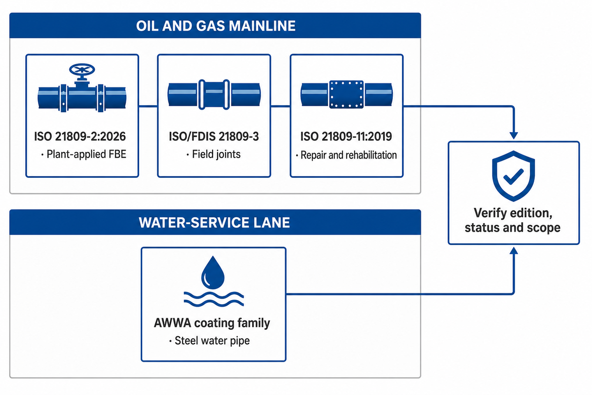
A standards citation becomes useful only when its service lane, coating location, document status, edition and exclusions match the purchase. Public scope pages can identify the correct family, but they don’t replace licensed acceptance clauses. Buyers should record what a document covers, what it doesn’t prove and which project document supplies the missing requirement.
| Public standard entry | Applies to | Does not prove | Buyer verification | Limitations / Not suitable for |
|---|---|---|---|---|
| ISO 21809-2:2026 | Plant-applied single-layer FBE; oil and gas transport | Field-joint coating or water-pipe acceptance | Edition, project clauses and offered system qualification | Not a general standard for every buried steel pipe |
| ISO/FDIS 21809-3 Ed. 3 | Approval-stage field-joint coating revision | Published final status or mainline 3LPE qualification | Current life-cycle status and project-adopted edition | Not a mainline multilayer coating standard |
| ISO 21809-11:2019 | In-field coating application, repair and rehabilitation | Field-joint coating requirements | Current confirmation and applicable repair scope | Not for field joints, which are addressed separately |
| AWWA C210 | Liquid-epoxy systems in its steel-water-pipe scope | Oil and gas transportation acceptance | Current edition, inside versus outside scope and project clauses | Not transferable beyond the stated water-service scope |
| AWWA C213 | FBE in its steel-water-pipe scope | ISO oil and gas mainline compliance | Edition, application location and acceptance tests | Not proof for another commodity lane |
| AWWA C214 | Tape coating in its steel-water-pipe scope | Suitability for every soil or installation method | System build, application and owner requirements | Not a generic tape approval |
| AWWA C215 | Extruded polyolefin systems in its stated scope | Mainline 3LPE acceptance for oil or gas | Current edition and full system qualification | Not interchangeable with other polyolefin systems |
| AWWA C216 | Heat-shrinkable polyolefin coating within its scope | Compatibility with any mainline coating | Joint geometry, substrate and procedure | Not a universal field-joint kit |
| AWWA C217 | Petrolatum and petroleum-wax tape systems in scope | Mechanical robustness for every installation | Owner specification and handling protection | Not a default new-line coating |
| AWWA C222 | Polyurethane coating in its steel-water-pipe scope | Potable-water approval or project fitness by name alone | Edition, contact requirements and product qualification | Not evidence outside the stated service scope |
Use the public map to find the lane, then purchase or access the adopted standard and copy the project-relevant acceptance clauses into the specification. Also keep the steel substrate boundary separate: line pipe substrate and grades describe the pipe body, while coating qualification and application records prove the external barrier.
Temperature, Soil and Chemical Exposure Set the Material Boundary
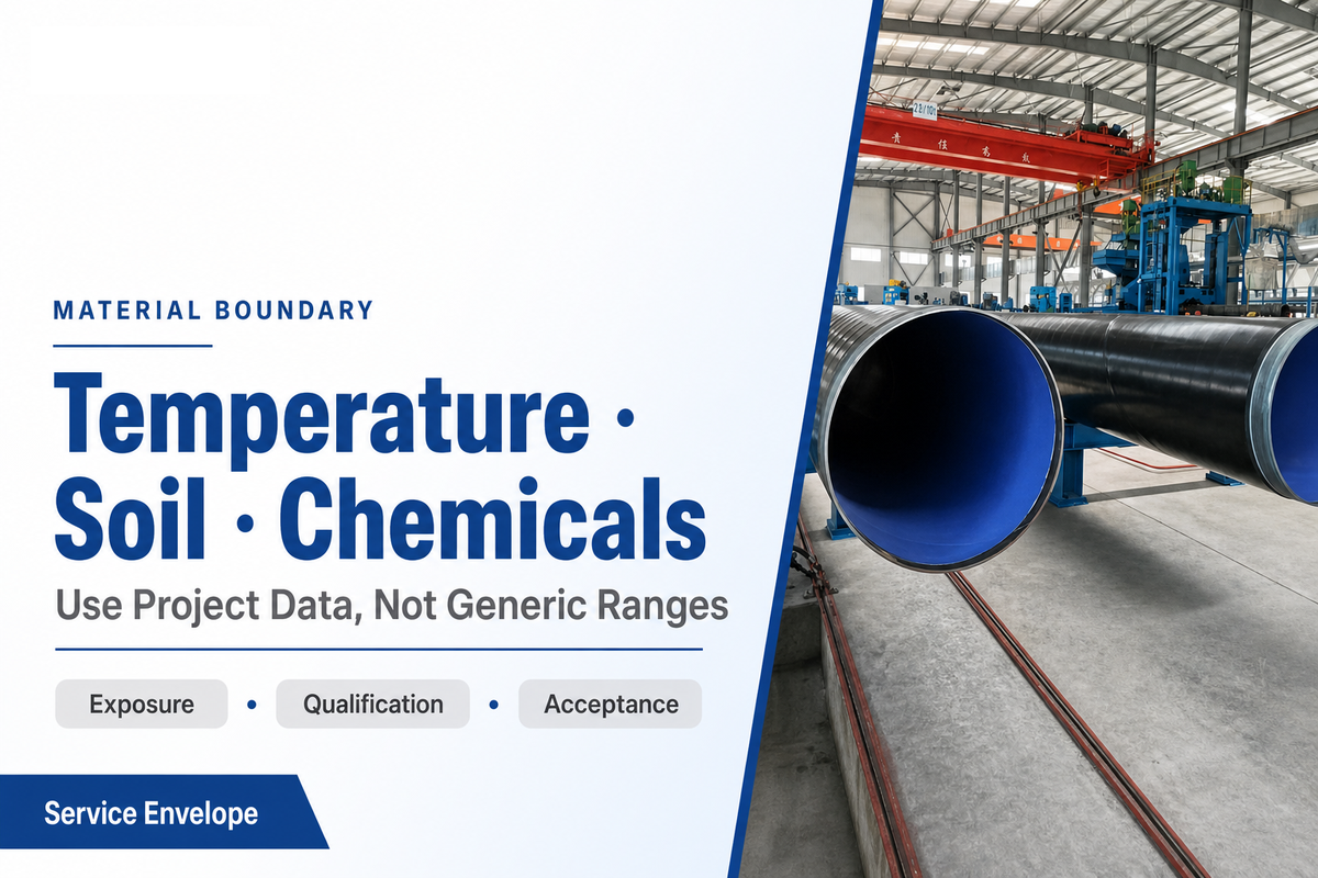
Temperature, soil and chemical exposure can disqualify a coating, but generic online ranges shouldn’t set the specification. Designers should state normal, upset and installation temperatures; groundwater and drainage; soil contaminants; microbial concerns; conveyed-medium consequences; and expected duration, then compare those inputs with qualified product and project data.
Environmental conditions should capture soil conditions, exposure to moisture, microbial activity and chemical contact. Separate damage from soil, moisture and corrosion, and impact and chemical exposure rather than compressing them into one severity label.
A soil description such as “wet,” “saline” or “rocky” is a screening signal, not a complete corrosion model. Soil resistivity, pH, chlorides, sulfates, moisture variation and microbiological activity may matter, but their interpretation belongs to the project’s corrosion assessment. Likewise, “chemical resistant” is incomplete unless the chemical, concentration, temperature, exposure mode and duration are named.
A National Academies review of buried steel infrastructure explains that physical barriers, cathodic protection, corrosion allowance and environmental control can work in combination. It also ties coating performance to exposure, surface preparation, adhesion, application and damage. One laboratory property or an unbounded service-life statement therefore can’t carry the decision.
Illustrative water-project scene: A 914 mm steel water main has 9.5 mm wall, 28 km of open trench, a 40 °C maximum water temperature and sections of seasonally saturated soil. Its asset lane first points the buyer to the AWWA family. Coating selection still needs external versus internal scope, potable-water contact requirements, joint design, backfill control and owner-specific acceptance evidence.
Installation Damage Can Change the Coating Choice
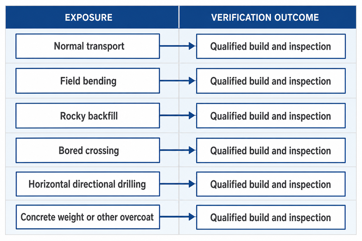
Installation damage can overturn a coating selected only for corrosion resistance. Transport racks, lifting, bending, abrasive or rocky backfill, bored crossings and horizontal directional drilling impose different abrasion, impact and gouging risks. Extra mechanical protection is justified when a documented damage mechanism, qualified system build and inspection plan support it, not when terrain is merely called harsh.
| Exposure | Damage question | Possible response | Verification | Limitations / Not suitable for |
|---|---|---|---|---|
| Normal transport | Are supports, straps and stacking controlled? | Approved handling and storage plan | Receipt inspection and damage log | Not proof of installation fitness |
| Field bending | Can the qualified build tolerate the bend procedure? | Procedure qualification and post-bend check | Recorded visual and discontinuity inspection | Not resolved by coating thickness alone |
| Rocky backfill | Can point loading, gouging or settlement damage the barrier? | Selected fill, padding or qualified overcoat | Backfill and placement records | Not justified by a soil adjective alone |
| Bored crossing | What contact occurs during insertion? | Qualified abrasion build and crossing plan | Pre-entry and accessible post-entry checks | Not a substitute for route-specific assessment |
| Horizontal directional drilling | What pull-through loads and formation contacts are expected? | Qualified ARO or multilayer response | Pull plan, coating checks and defined indirect evidence | Not fully inspectable after pullback in many routes |
| Concrete weight or other overcoat | Are interfaces and application steps compatible? | Project-qualified multilayer build | Interface procedure and acceptance record | Not covered by a mainline coating name alone |
PHMSA’s coating overview notes that coating may be damaged during installation and that field girth welds require coating during construction. AMPP’s HDD discussion adds a practical limit: after pull-through, direct access may be restricted. Therefore the project should move verification forward into handling qualification, pre-pull inspection, monitored installation and defined post-installation evidence.
Coating and Cathodic Protection Work as One Integrity System
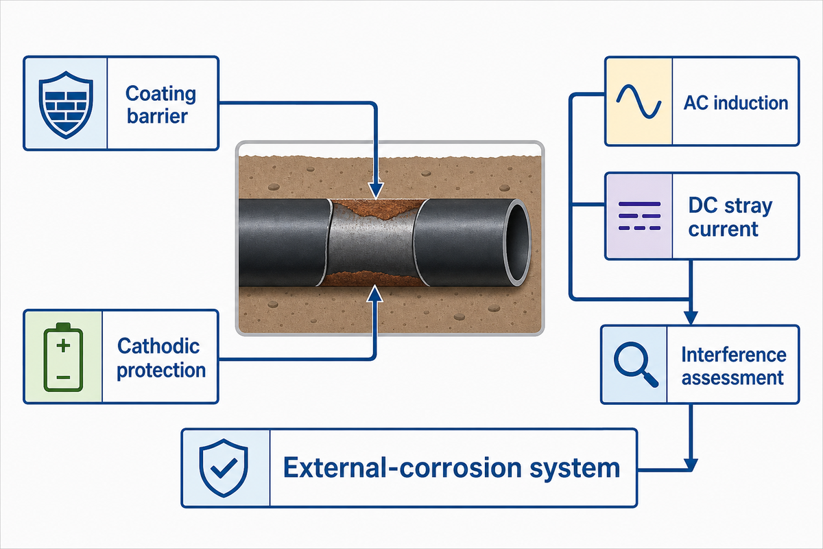
Coating and cathodic protection are complementary controls, not substitutes. Coating limits the area exposed to the electrolyte; cathodic protection acts at holidays or other exposed steel where designed. Compatibility, disbondment behavior, electrical continuity, shielding risk, monitoring access and installation damage must therefore be evaluated as one external-corrosion system.
Cathodic protection systems contribute to protection against corrosion, but they do not by themselves prevent corrosion at every coating defect.
An AMPP cathodic-protection resource explains that coatings and CP are commonly used together and that inspecting the coating helps the CP system perform as designed. That relationship does not authorize a generic potential, current density or monitoring interval. Required figures depend on the asset, jurisdiction, standard and qualified design.
Electrical interference is a separate branch. A peer-reviewed review of AC corrosion on buried carbon-steel pipelines reports that alternating-current corrosion can occur even when conventional cathodic-protection criteria are met. A shared right-of-way, overhead transmission line, electrified rail or DC source therefore needs an interference assessment; a passing conventional CP criterion alone is not proof of AC protection.
Field Joints and Repairs: The Coating Continuity Chain
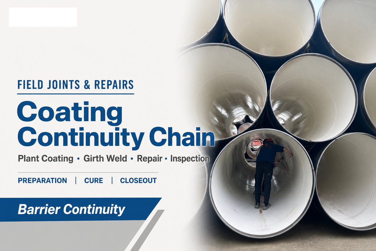
A buried-pipeline coating system is incomplete until the plant coating, girth-weld coating, repair material and inspection hold points are compatible. Cutback geometry, surface preparation, application window, overlap, cure, repair size and discontinuity inspection should be specified as a continuity chain, then traced in field records from each joint to final acceptance.
Field-joint coating faces the same pipe, service, soil, construction and cathodic-protection variables as the mainline system.
Standards boundaries reinforce the point. ISO’s page for ISO/FDIS 21809-3 Edition 3 identifies a field-joint coating document at approval stage. Its page for ISO 21809-11:2019 covers in-field application, repair and rehabilitation but explicitly leaves field joints to Part 3. A buyer should not cite “ISO 21809” as though every part covers the same work.
- Approve the mainline cutback and joint geometry.
- Qualify substrate preparation and environmental limits.
- Verify material identity, storage condition and shelf control.
- Record application, overlap and cure against the approved procedure.
- Inspect discontinuities and adhesion using project-defined methods.
- Close repairs and nonconformances before burial.
Illustrative field scene: A 1,067 mm line arrives with a factory multilayer coating and a 150 mm cutback at each pipe end. Site staff cannot choose a sleeve solely because the width looks adequate. An approved package must match substrate preparation, mainline surface, 45 °C ambient application conditions, overlap geometry, cure evidence, repair method and the project’s inspection procedure.
2026 Standards Status: Freeze the Edition Before You Buy
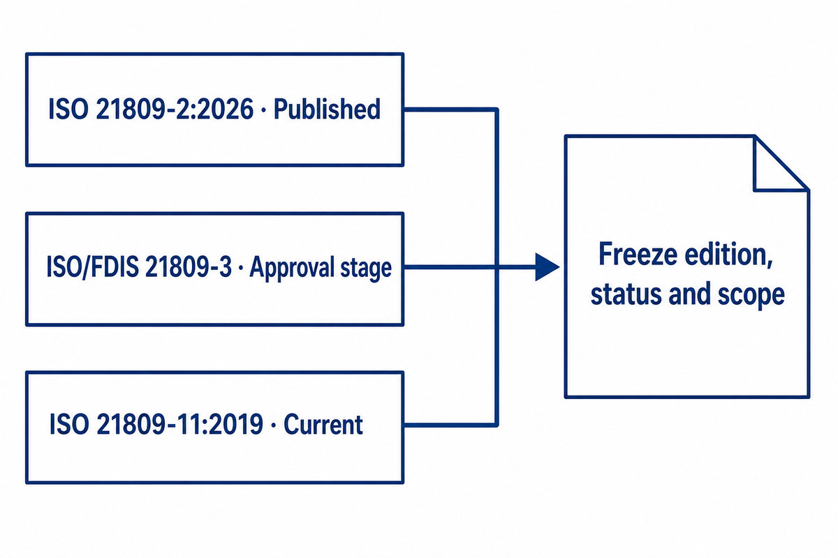
Current 2026 standards status makes edition control a live procurement issue. ISO 21809-2 Edition 3 was published in February 2026, while ISO/FDIS 21809-3 Edition 3 entered the approval stage in June 2026. ISO 21809-11:2019 remains current after its 2025 confirmation.
A bare part number can therefore conceal different status and scope.
Record four items in the request for quotation: full document number, edition or publication year, status, and the clauses adopted by the project.
If a supplier cites a draft or predecessor, require a deviation statement explaining the technical effect. If a contract names an older edition, the buyer must resolve the contract basis rather than silently swapping in a newer page found online.
For 2026 projects, re-check status at bid issue, technical clarification and purchase-order release. This isn’t a claim that every new edition changes product performance. It’s a document-control measure that prevents factory coating, field joints, repair and inspection from being accepted against mismatched scopes.
Inspection and RFQ: The Five-Document Acceptance Pack
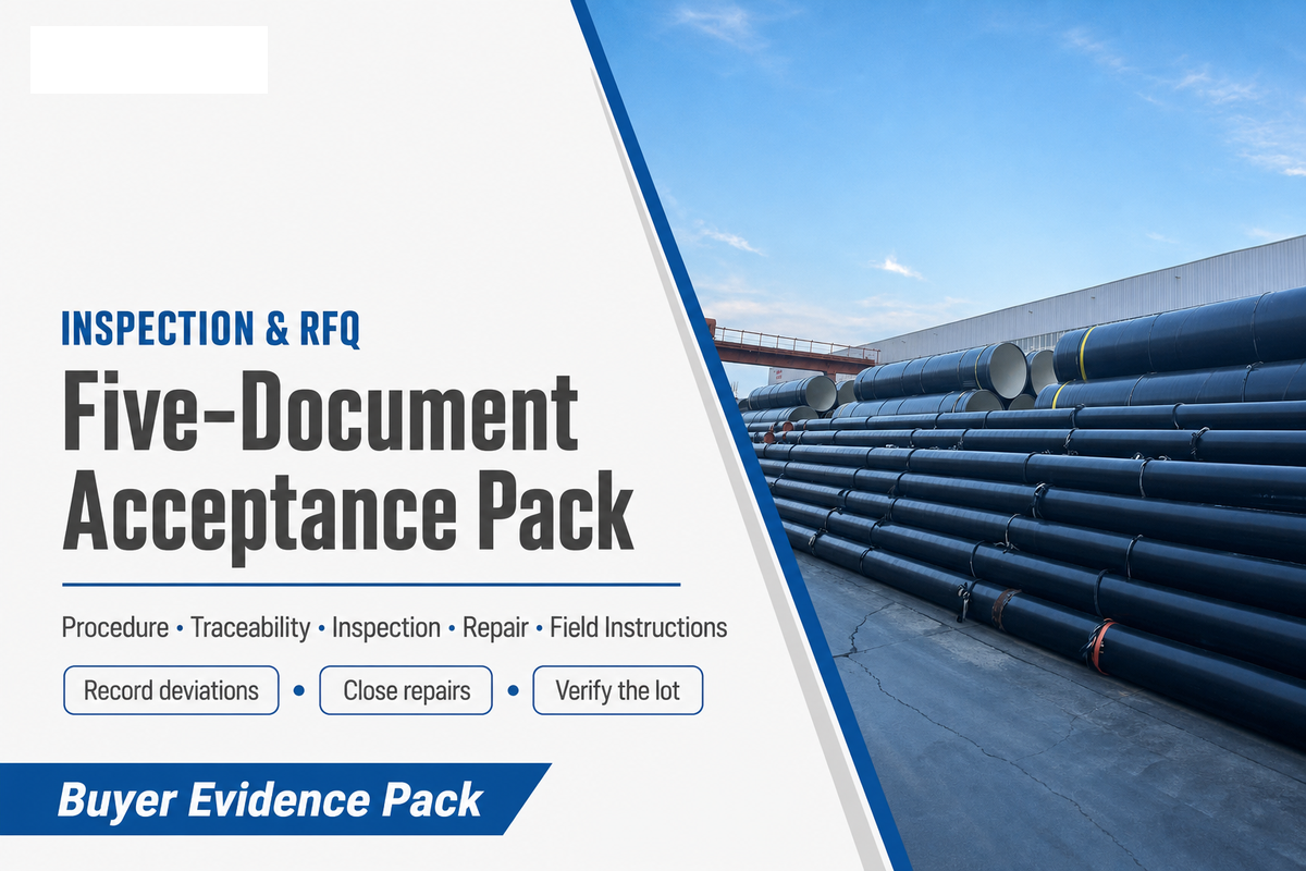
Our Five-Document Acceptance Pack turns a coating name into auditable supply evidence. It should contain the approved procedure and product data, material and batch traceability, application and inspection records, nonconformance and repair closure, plus handling, storage, and field-joint instructions.
Exact tests and thresholds must come from the adopted project documents.
Copy this checklist into the request for quotation, then replace each project-value prompt with controlled data before release.
Buried steel pipe coating RFQ checklist:
| Parameter | Required entry | Why it matters | How to verify |
|---|---|---|---|
| Asset and medium | Commodity, jurisdiction, design code | Selects the standards lane | Design basis and line list |
| Pipe identity | Outside diameter in mm, wall in mm, grade, manufacturing route | Controls application and handling basis | Purchase specification and traceability |
| Temperature | Normal, design and upset values in °C or °F | Screens qualified material envelope | Approved product data and qualification record |
| Burial environment | Soil, groundwater, contaminants, microbial concern | Defines exposure and investigation needs | Geotechnical and corrosion survey |
| Installation | Transport, bend, backfill, bore or HDD length in m | Sets mechanical-damage controls | Method statement and qualification evidence |
| Electrical and CP interface | CP basis, AC and DC interference screen | Prevents a coating-only integrity claim | Qualified engineering review |
| Field joints and repairs | Materials, preparation, cure, overlap, repair limits | Maintains coating continuity | Approved procedures and field records |
| Acceptance | Adopted clauses, tests, hold points and records | Defines release evidence | Inspection and test plan |
- Name the full standard, edition, scope and clauses.
- Require offered-system qualification and batch traceability.
- Define field-joint, repair and inspection ownership.
- Record deviations before purchase-order release.
- Use “ISO compliant” as a complete requirement.
- Transfer a water-pipe scope to oil or gas service.
- Assume cathodic protection excuses coating damage.
- Accept an unsupported lifetime or temperature promise.
For underground applications, long-term protection comes from the verified system rather than the coating name. For a conditional commercial option, review Baling Steel’s FBE coated pipe offering and ask for project-specific conformity evidence. Baling Steel also describes professional inspection resources; those company statements support a capability discussion, while the delivered lot’s records remain the acceptance proof.
Select buried steel pipe coating by service lane and seven project inputs, then purchase a compatible mainline, field-joint, repair, cathodic-protection and inspection system.
Prepare a coating quote that engineering can review
Send the medium, pipe size and grade, normal and design temperatures, route and installation method, soil and backfill data, governing standard, field-joint concept and required inspection pack.
Frequently Asked Questions
What are the different types of pipeline coatings?
External pipeline coating families include FBE, reinforced FBE, multilayer polyolefin, liquid epoxy, tape and project-specific field systems; service, installation, cathodic protection, joints and standards determine the shortlist.
What is the best coating to prevent galvanic corrosion?
No coating name universally prevents galvanic corrosion; coupled materials, electrical continuity, electrolyte, coating condition and cathodic-protection design control the risk for the specific connection and service.
Is FBE or 3LPE better for buried steel pipe?
FBE and 3LPE are conditional choices: 3LPE adds adhesive and polyethylene layers, while FBE is bonded epoxy; temperature, installation, field joints and project standards decide.
When should an abrasion-resistant overcoat be specified?
Specify an abrasion-resistant overcoat when a documented installation mechanism can damage the primary barrier, a qualified build addresses it and project inspection can verify protection.
Why do field-joint coatings need their own specification?
Field-joint coating closes the corrosion barrier at girth welds and must match the mainline coating under specified preparation, overlap, cure, repair and inspection controls for the adopted project standard.
What documents belong in a buried-pipe coating RFQ?
A buried-pipe RFQ needs the design basis, standard edition, approved coating procedure, traceability, inspection records, deviation list, repair closure and field instructions for the intended installation method.
References & Sources
- ISO 21809-2:2026 public scope International Organization for Standardization
- ISO/FDIS 21809-3 Edition 3 public scope and status International Organization for Standardization
- ISO 21809-11:2019 public scope International Organization for Standardization
- AWWA Standards List: Steel Pipe and Fittings American Water Works Association
- 49 CFR Part 192, Subpart I Electronic Code of Federal Regulations
- Pipe Coatings fact sheet Pipeline and Hazardous Materials Safety Administration
- Corrosion of Buried Steel at New and In-Service Infrastructure National Academies
- Cathodic Protection for Corrosion Control Association for Materials Protection and Performance
- AC corrosion of cathodically protected buried pipelines Materials, peer-reviewed review
- The Hidden Damage Done to Protective Coatings Materials Performance
- Field Joint Coatings Materials Performance