Welding stainless pipe requires a different mental approach than working with carbon steel. That same chromium that allows stainless to hold up against corrosion is a detriment when heat is applied to it — and all welds are a predetermined dosage of it. Whether through the welding processes used, the choice of filler metal, the methods of purging or testing standards, here is what makes a welded stainless steel pipe joint corrosion resistant, rather than failed prematurely.
Quick Specs
| Primary Process | GTAW (TIG) for root pass; GMAW/FCAW for fill & cap |
| Shielding Gas | 100% Argon (TIG); Ar + <5% CO₂ blends (MIG) |
| Filler Grade | ER³08L (304 base), ER316L (316 base), ER309L (dissimilar) |
| Back Purge Gas | 99.99% Argon — target <25 ppm O₂ (food-grade) |
| Key Standards | ASTM A312/A312M-22, ASME Section IX, AWS D18.1:2020 |
| Ma× Heat Input | <1.5 kJ/mm for austenitic grades |
| Interpass Temp | ≤350°F (177°C) per ASME guidelines |
Why Stainless Steel Pipe Welding Is Different from Carbon Steel
Carbon steel forgives poor heat control. Stainless steel does not. There are three metallurgical aspects that render welding stainless pipe a totally new process:
Chromium sensitivity. Stainless steel has 10.5% or more chromium in it (by weight). This deposits a chromium oxide (Cr0) protecting layer on the surface—the reason it is “stainless”.
Welding ‘breaks’ that protective layer and, if not done properly, stops it reforming.
Sensitization. Long exposure to above 950F (500C) and 1500F (800C) temperatures allows the carbon to alloy with the chromium leading to the formation of chromium carbides along the grain boundaries. This “wastes” the chromium so that chromium oxide does not develop – another form of corrosion called sensitization.
Conditions can result in hole pinhole leaks in a matter of months.
Thermal conductivities. One class of steel that is 30% poorer than carbon steel at conducting heat is the austenitic stainless steels. They process the ability to concentrate heat to the centre line, rather than expanding to away from it.
The effect on distortion is compounded and requires a welders best skill and ‘dead-on’ interpass temperatures until the knowledge of the differences is understood. Neither is preferable, both must be able to accomplish corrosion resistant welds on either type of pipe.
TIG vs MIG vs Flu×-Core: Choosing the Right Welding Process for Stainless Pipe
The weld process affects joint quality, productivity and ultimately cost. TIG welding stainless steel pipe via gas tungsten arc welding (GTAW) is still king for root passes; however, altered MIG processes are beginning to upset the balance for fill and cap passes—and in some instances, for root passes also.
| Parameter | GTAW (TIG) | GMAW-RMD (Mod. Short Circuit) | FCAW (Flux-Core) |
|---|---|---|---|
| Travel Speed | 3–5 ipm | 6–12 ipm | 8–15 ipm |
| Back Purge Required? | Yes (always) | Sometimes eliminable (austenitic only) | No (flux scavenges carbon) |
| Shielding Gas | 100% Argon | Ar + <5% CO₂ or Tri-Mix | 75% Ar / 25% CO₂ |
| Skill Level | High (weeks of training) | Moderate (days of training) | Moderate |
| Best Application | High-purity, sanitary, ≤6″ dia. | Structural, oil & gas, ≥8″ dia. | Field repair, non-critical |
Process Selection Decision Framework
- TPP-Sanitary/food-to-3a pipe T I G only(autogenous square butt weld for wall< 1/8″, filler metal for heavier)
- Structural / industrial SCH 40 TIG root + pulsed MIG or FCAW fill and cap (good productivity balance)
- But…string a large diameter (>8″) non-critical RMD root (maybe even purge free) + pulsed MIG fill.
- Thin-wall tubing, 0.4″Wgt,≤0.065″ TIG, highh.frequency pulse(250-400 pps for 35% speed up)
- Dissimilar SS to CS joint TIG using ER309L filler (dilution control important)
What Is the Best Way to Weld Stainless Steel Pipe?
It really comes down to the application. When handling pharmaceutical and food-grade piping that needs to conform to AWS D18.1:2020 specifications, TIG welding with complete argon back purge is the sole approach. However, when working with structural and oil-and-gas piping, a hybrid process of TIG root with pulsed MIG or flux-cored fill and cap offers the ideal mix of quality and productivity.
This removes the hot pass at TIG, and with ERW pipe and larger diameters, it can reduce welding time by 40-60%.
Filler Metal Selection — ER308L, ER316L, and the “L” Grade Rule
The most damaging thing you can do to the corrosion resistance of a stainless weld deposit is to use an incorrect filler. Fit up and welding conditions are not critical compared to filler metal chemistry. The correct filler chemistry for a stainless is that of the base metal which, in most instances, is lower in carbon than the filler.
| Base Metal | Filler Metal (TIG/MIG) | AWS Spec | Max Carbon % |
|---|---|---|---|
| 304 / 304L | ER308L | AWS A5.9 | 0.03% |
| 316 / 316L | ER316L | AWS A5.9 | 0.03% |
| 321 (Ti-stabilized) | ER347 | AWS A5.9 | 0.08% |
| 304 to Carbon Steel | ER309L | AWS A5.9 | 0.03% |
But what about the “L”?
It can be read as “low carbon” which is a range up to 0.03% whereas the standard ER308 contains 0.08%. The concept is important: too much carbon can be present in the weld pool where it combines with chromium to produce chromium carbides which lead directly to unsatisfactory corrosion resistance.
If you weld a 304L base metal with a conventional 308 filler you will actually increase the carbon level in the joint and potentially increase the risk of corrosion. In high purity applications (>99%) such as food, beverage, and pharmaceutical this low carbon content is absolutely essential for corrosion resistance.
— MillerWelds Technical Article, American Welding Society / Welding Journal
📐 Engineering Note
Besides controlling the carbon content, stray elements (tramp elements) can be chosen in a few filler metals at low levels — tin, antimony, arsenic, phosphorus and sulfur. According to AWS A5.9 specification, these residuals of raw filler materials can cause wide corrosion to be very high although carbon content is in specifications. For further fluidity and high travel speeds, additional silicon was added into ER309LSi.
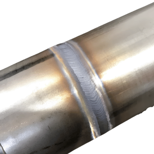
Back Purging — The Step That Separates Good Welds from Failures
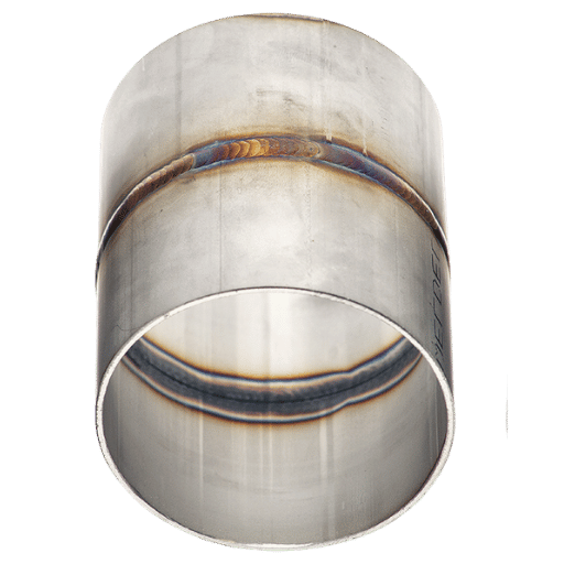
If you weld stainless pipe without shielding the interior surface, oxygen combines with the molten root and creates heavy oxide scale, a coarse black discolor welders refer to as “sugaring.” Sugared roots are cosmetically unacceptable but also represent chromium loss, making the joint a corrosion start point. Proper back purge of argon gas addresses this — it prevents oxidation by pushing out oxygen before the arc hits.
Never use 75/25 Ar/CO as a purge gas. Under industry experience, the practice of using CO containing gas to purge caused more problems then not using any purge at all – The carbon dioxide will decompose, accelerating carbon entering the root, and actively sensitizing the weld internally.
The 3-Zone Purge Test — Verify Before You Strike
Prior to ignition, ensure purge quality is good by testing three positions of the pipe:
- Zone 1 — Root (weld joint): Use an O₂ analyzer at the joint opening. Target readings depend on application:
- Farmacêutico: < 10 ppm O (conforme AWS D18.1:2020)
- Food-grade / sanitary: <25 ppm O₂
- Generelle industri kan: < 500 ppm O (noen verksteder tar imot < 1 000 ppm)
- Zone 2 – Mid-Pipe (dam location): Check the purity of the purge dam seal. Allowing in ambient air will contaminate the purge zone.
- Zone 3- Far-End – (exit vent): Gas is confirmed to escape at the far-end. If there is no flow, the purge is not flow down into the weld zone- you are welding a dead atmosphere.
On large diameter (16″) pipe, the actual practical purge arrangements can have a significant affect. An experienced pipe welder would suggest injection of the purge gas at the shortest end, venting at the top, on the far side, with a gas flow of 20 – 30 CFH. Calculate pipe internal volume to determine purge time – five volume changes is the -6 rule of thumb before checking on levels.
Heat Input, Sensitization, and Preserving Corrosion Resistance
All stainless pipe welds are a race against sensitization. As the HAZ stays between 950F & 1,500F (50-800C) the more chromium carbides form -and the more the joint compromises corrosion resistance. Managing heat input is not a job option, it is your primary engineering parameter to prevent in-service failure.
📐 Engineering Note — Heat Input Calculation
Heat Input (kJ/mm) = (Volts Amps 60) / (Travel Speed mm/min 1,000)
Example: 12 V 120A 60 / (150 mm/min 1,000) = 0.576 kJ/mm
Goal: <1.5 kJ/mm for austenitic grades. For best performance lower is better – modern TIG inverters with high-frequency pulsing (250-400 pps) can run by with lower average amperage and reduced heat input while still achieving excellent weld penetration, raising travel speed by as much as 35%.
How to mitigate sensitization through practice. First, choose low-carbon (“L” grade) filler metals and base metals to starve the chromium carbide reaction of its carbon feedstock. Second, limit interpass temperature – never exceed the maximum listed on your WPS; for austenitic grades, this is usually 350F (177C). Third, employ stabilized grades like 321 (titanium) or 347 (niobium). When the alloying elements combine with carbon to form stable compounds, the chromium remains free to form protective carbides. Be aware, however, that the stabilizers may compromise toughness and strength, making them inappropriate for certain projects.
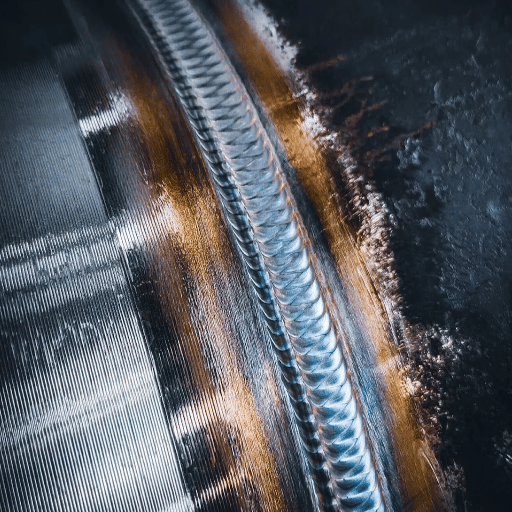
Root Pass, Hot Pass, Fill and Cap — A Position-by-Position Breakdown
Multi-pass pipe welding occurs in a systematic order. Each pass has a specific function, and must be controlled in different ways.
Root (GTAW). The initial pass is the most important – this provides full weld penetration and the backbone of the joint. Use the lowest amperage that will result in fusion and bead build-up (see below); many welders report 35-45 amps on thin-wall Schedule 10 pipe with no pulse, a 6-second downslope, and a 5-8 second off-flow gas kick. Speed of travel should be even, keeping the weld puddle narrow and controlled. On this critical pass the most common mistake is burning through. Burn-through creates an uncontrollable root, then thick excess building on top makes sanitary flow restrictions worse.
Hot (or “warm”) pass. Immediately following the root, this pass smooths and stamps the root profile, while burn out any slag inclusions. Use an A or B amperage ratio over the root; travel faster than the root. Some pig makers skip the hot pass when they don’t switch from TIG to RMD which grows a cleaner root profile, so there is less slag to get burned out.
Fill and cap passes where the welding is done to build up the joint to the throat thickness needed. Flux-cored or pulsed MIG wires are often used on structural stainless, using the same shielding gas and wire as in the root to keep idle times down; stringer beads instead of weaving minimize heat input. Each pass must cool to below the interpass temperature limit before the next one is laid down.
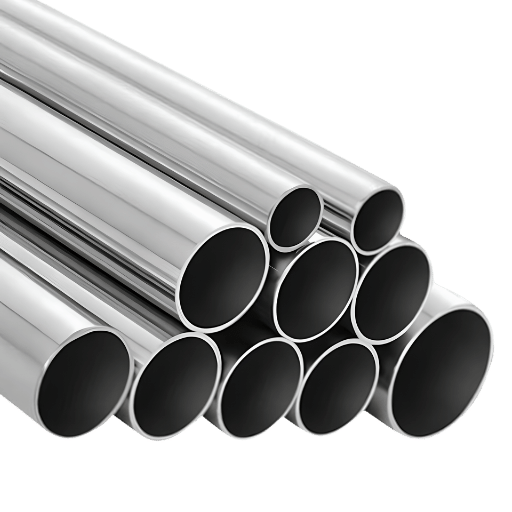
Is It Better to Weld 304 or 316 Stainless Steel?
In terms of weldability, 304 and 316 are very similar – both are austenitic, and both require no more than the basic precautions against sensitization and oxidation. The only practical difference is that 316 has 2-3% molybdenum for improved alloying with chloride solutions that lead to pitting and crevice corrosion. Classically, the hard to weld, high corrosion-resistance applications (salt water, chemical processing, marine environments) use 316L pipe with ER316L filler. For all other uses – structural supports, water lines, food processing lines – using the less expensive 304L with ER308L filler produces a weld with identical properties.
Welding Stainless Steel to Carbon Steel — Dissimilar Metal Joints
Joining stainless pipe to carbon steel is a common need at transition points – for example, where a stainless process line connects to a carbon steel structural header. The main concern is carbon migration: carbon from the carbon steel side diffuses into the stainless steel weld zone, increasing the carbon content and producing a sensitized band vulnerable to corrosion.
ER309L filler metal addresses this issue. Its elevated levels of chromium and nickel result in a weld deposit that tolerates the dilution from the carbon steel side while maintaining corrosion resistance on the stainless side. TIG offers the best control over dilution levels. To minimize pickup from the carbon steel side, slightly drag the arc toward the stainless steel. For most applications, MIG provides adequate control.
Preheat the carbon steel side to 200-300F (93-149C) for wall thickness greater than 3/4”. Do not preheat the stainless steel side – preheating excessively thickens the sensitization zone. Depending on pipe size and pressure class, either butt weld fittings or socket weld joints are used at the transition point.
Can I Use 7018 on Stainless Steel?
No – E7018 is a low-hydrogen carbon steel electrode and, in the context of stainless to stainless or stainless to carbon steel, deposits carbon steel weld material in the weld pool. This produces a high-carbon, no-chromium deposit, and a subsequent stainless joint that has a high propensity to corrosion. For stainless to stainless, select E308L-16 (SMAW) or ER308L (TIG/MIG). For stainless to carbon steel, select E309L-16 (SMAW) or ER309L (TIG/MIG). E7018 is never appropriate.
WPS, PQR, and ASTM A312 — Standards and Procurement Specifications
Quality welding on code-governed stainless pipe requires a Welding Procedure Specification (WPS) that is qualified through a Procedure Qualification Record (PQR). ASME Section IX is the governing document that specifies the critical variables requiring qualification.
- WPS critical variables: P-Number (the base metal group), F-Number (the filler metal group), A-Number (the weld metal chemistry), PWHT requirements, wall thickness range, position, and shielding gas composition
- PQR: Describes the test weld and summarizes results from the mechanical testing (tensile, bend, impact) and visual/NDE inspection processes to demonstrate that the WPS produces a suitable weld
- Welder Qualification: Each individual welder must conduct qualification tests in the positions (2G, 5G, 6G) in which he will be welding per ASME Section IX or AWS D1.6
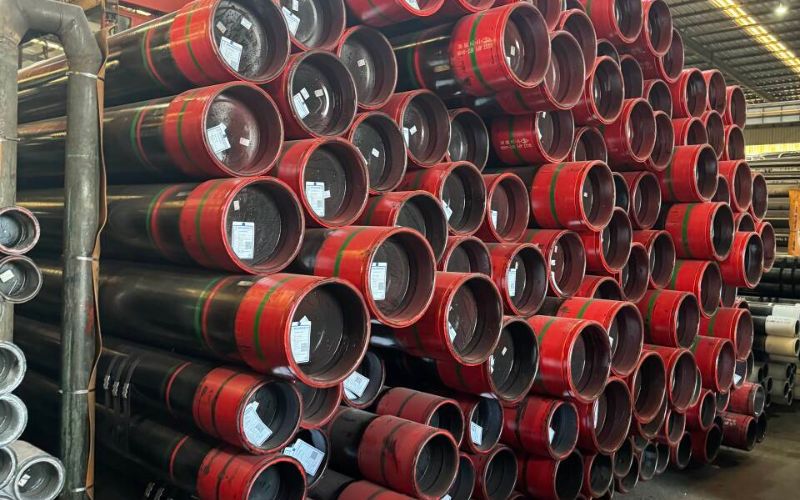
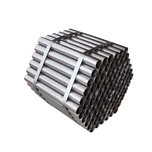
When ordering stainless welded pipe, specify ASTM A312/A312M-22 – the current specification for welded and cold worked austenitic stainless steel pipe. Typical stainless pipe grades are TP304, TP304L, TP316, TP316L, and TP321. Typical diameters are from 1/8″ to 30″ and wall from Schedule 10S to Schedule 80S. Make sure to always order your MTR/MTC per EN 10204 Type 3.1 so you can review the chemical composition and mechanical properties from the mill prior to welding it.
Common Weld Defects, Prevention, and Post-Weld Treatment
Even the best of welders will produce imperfections on stainless pipe. When you recognize these flaws early your entire project can save by not re-welding (at best) or the weld failure in service.
| Defect | Root Cause | Prevention |
|---|---|---|
| Sugaring (oxide scale) | Inadequate or missing back purge | 3-Zone Purge Test; O₂ <25 ppm before welding |
| Sensitization | Excessive heat input; high carbon filler | “L” grade fillers; interpass temp ≤350°F; minimize passes |
| Hot cracking | Low delta-ferrite in fully austenitic welds | Maintain 3–8 FN ferrite; control restraint; avoid concave beads |
| Porosity | Contamination; insufficient shielding gas | Dedicated SS brushes/grinders; verify gas flow 15–25 CFH |
| Lack of fusion | Low amperage; poor joint prep; excessive gap | Proper bevel (37.5° ± 2.5°); fit-up gaps <1/16″; adequate amps |
Post weld treatment. Once the weld is complete on your stainless pipe, you will want to passivate it. ASTM A380 has guidance on cleaning, descaling, and passivating stainless pipe. This passes mitigation step generally consists of a nitric-hydrofluoric acid pickling step or similar process to remove heat tint and free ferric iron content, and a post passivate in a nitric acid or citric acid solution. If this welded pipe is for the pharmaceutical industry, the smoothest internal surface finish (Ra 0.5 m) you can achieve in these post heat treatment steps using electropolishing will meet the most demanding Pharmaceutical requirements of a commonly used international standard by far. Always use visual inspection or dye penetrant examination, and where appropriate based on code, RT or PT examination to triple check the weld completion.
Stainless Welded Pipe Market: What’s Changing in 2025–2026
The demand is ramping up. From 2025 through 2035, the annual growth rate ( CAGR) of US welded stainless pipe will be 4.3% fueled by the increase in pharmaceutical manufacturing capacity, new water treatment infrastructures and LNG processing capacity increased. On the worldwide level, the growth trend is even steeper – a CAGR of 12.8% forecasted from 2026 to 2033, fueled by the increased needs of SE Asian and Middle Eastern industries.
Two evolution are noted. One is the increased availability of orbital welding systems outside pharmaceutical applications and these systems are being used more and more in the fabricated piping industry. A chronic shortage of qualified pipe welders – has been noted in the AWS 2026 Welding Industry Outlook and this gap combined with the sensitivity of TIG welding to welder skills requires the use of automation to be more economically viable. The other is the adoption of modified short circuit type MIG processes like RMD replacing TIG in non-critical structural applications thus reducing installation time as well as back purging requirements.
If you are considering piping projects in 2026-2027, now is the time you should be looking into this technology. Payback period has shortened as the project welder labor rate has risen and the consistency of these systems is inherently more repeatable than manual TIG for high numbers of repetitive welds.
Frequently Asked Questions
Q: Can stainless steel pipes be welded?
View Answer
Q: What shielding gas do you use for stainless pipe welding?
View Answer
Q: Is stainless pipe welding safe?
View Answer
Q: How do you prevent discoloration when welding stainless pipe?
View Answer
Q: What is the difference between ER308 and ER308L filler metal?
View Answer
Q: Do stainless pipe welds need to be stress relieved?
View Answer
Precure stainless steel welded pipe to project specification requirements.
Baling Steel supplies ASTM A312 TP304/TP304L/TP316/TP316L welded pipe from 1/8″ to 30″ OD with Mill Test Certificates per EN 10204 Type 3.1.
About This Analysis
Baling Steel manufactures Edelstahl art welded pipe and fittings. The welding practice, filler metal specifications and acceptance criteria are summarized from AWS, ASME and ASTM published welding codes, extracted and cross referenced with authoritative welding technical literature. We are not a welding consulting practice, we present facts so that our customers, fabricators, EPC contractors and maintenance crews, can accurately specify Baling Stainless products.
References & Sources
- ASTM A312/A312M-22, Austenitic Stainless Steel Pipe, Welded and Cold Worked Grades, ASTM International
- AWS D18.1/D18.1M-2020, Specification for Welding of Austenitic Stainless Steel Tube and Pipe Systems for Sanitary Applications, American Welding Society
- AWS A5.9, Filler Metal Classification for Stainless Steel, American Welding Society
- Corrosion Resistance of 304 Austenitic Stainless Steel Welded Joints,National Institute of Health / PMC
- Hot Cracking Sensitivity Factors in Austenitic Stainless Steels, Total Materia
- The Future of Welding, Trends, Technology and Industry Outlook, American Welding Society
- Analysis of 2025-2035 demand for Stainless Steel Welded Pipe in the US, Future Market Insights
Related Articles
- ERW Pipe, Manufacturing Process, Standards & Usage.
- Welded and non-welded Stainless Steel Pipe – which is the best choice?
- 304 stainless steel, properties, grades and specifications.
- Stahlschmittengrößen und Maßen Chart
- Drill bits for Stainless Steel- Help on the correct speed and the best material for use.
Check by the Baling Steel engineering group. Updated to date: April 2026.