Weld neck flanges are industry favorites due to their strength and dependability in the oil and gas, petrochemical, and power plants sectors. Their ability to withstand enormous pressure and heat makes them indispensable in these fields. Whether you are an engineer, procurement officer, or simply someone from the industry, appreciate the understanding of the advantages, applications, and reasons for utilizing weld neck flanges. In this article, we will describe everything you need to know about weld neck flanges, their distinctive design, most common uses, and what makes them a favorite in harsh industrial conditions. By the end of this guide, you will know why the weld neck flanges are crucial in enabling safe piping system operations.
What is a Weld Neck Flange?

A weld neck flange is a specific type of flange primarily utilized in piping systems with high pressure and temperature. The flange is characterized by its long, tapered hub, which provides added strength as well as a strong connection while being welded to the pipe. This helps reduce the concentration of stress, which makes it more useful for demanding applications. Weld neck flanges are mainly used in the oil and gas, petrochemical, and power generation industries, where reliability and endurance are crucial.
Understanding the Weld Neck Flange Design
The weld neck flange has a smooth transition from the flange face to the neck, which is achieved via the tapered hub. This characteristic helps to improve the mechanical strength of the flange by increasing the stress concentration at the base of the flange. The flange overhanging has a bevel that is joined to the pipe, ensuring a strong connection without leaks (satisfactory for leak testing). Its capacity to endure intense pressures, severe temperatures, and difficult surroundings makes it highly dependable for critical applications. Further, the weld neck flange is meant for ultimate precision and performance in the most challenging industries.
How Does a Weld Neck Flange Work?
The operational principle of a weld neck flange consists of a stronger pipe and flange connection through butt welding – a seamless joint. Weld neck flanges have a long, tapered hub that gives a weld neck flange a gradual transition from the thickness of the flange to the pipe. The mechanical stresses due to elevated temperature and pressure fluctuations are evenly distributed throughout the entire flange and pipe assembly because of the tapering.
Within the weld neck welding procedure, the flange bevel is aligned to the corresponding edge of the pipe, and full-penetration welding is executed. This procedure guarantees that the likely risks of leaking or failing under stressful operating conditions are all but eliminated due to the secure connection provided. Given the high positioning of the neck, the flange is widely preferred for use in pipelines that transport a fluid or gas under high pressure or extreme temperatures externally.
For items like weld neck flanges, other key specifications are usually combined with others, such as with ASME B16.5 for grades ½ inch to 24 inch and above, based on system need. Furthermore, for these flanges, pressure rating is greatly exceeding that of Class 2500 (approx. 6000 PSI) and functioning temperatures under 1000°F, while strongly depending on the material used, carbon steel, stainless steel, and alloy steel, to meet certain industrial requirements.
Weld neck flanges are important in applications like oil and gas, petrochemical processing, power generation, and marine engineering because they are optimized for flow efficiency and can withstand tough conditions. Their precise construction and performance are essential to operational safety and reliability in demanding environments.
Why Choose Weld Neck Flanges?
Weld neck flanges are ideally suited for applications with high pressure and temperature due to their robust and lasting relationship. The design of neck flanges minimizes stress concentration at the neck and provides smooth fluid passage, which reduces turbulence and erosion risks. Furthermore, their reliability in providing leak-proof connections renders them preferred in defense industries like oil and gas, power generation, and petrochemicals. Their performance adaptability in various operating environments with stringent requirements enhances cost-effectiveness in tough environments.
Benefits of Neck Flanges in Pipelines

Role of Neck Flanges in High-Pressure Systems
Neck flanges serve an important purpose in high-pressure systems as they form reliable and robust joints between pipes, valves, and other pieces of equipment. The tapered neck geometry of neck flanges assists in stress distribution, minimizing the possibility of failure due to excessively high pressure. Furthermore, neck flanges improve the overall strength of the entire pipeline, which is vital for safety and operational efficiency when working under high-pressure conditions. Their unmatched dependability and accuracy make them suitable for use in almost all sectors.
Advantages Over Other Flange Types
Enhanced Strength and Reliability
- Neck flanges are tailored to provide unmatched mechanical strength and stability. Because of their tapered and beveled flare, stress is distributed evenly, which reduces the chance of failure in extreme scenarios. Research suggests that neck flanges have stress resistance 25-30% greater than flat face or slip-on flanges.
Superior Sealing Performance
- Neck flanges retain excellent sealing capabilities because of their longer hub, which is critical for applications that require airtight and watertight systems. This is highly favored in the oil and gas industry, which faces significant safety and environmental risks from leaks.
High-Temperature and High-Pressure Tolerance
- Neck flanges can withstand extreme temperatures, intense pressures, and operate efficiently in high heat. Their ability to endure beyond 5000 PSI and 1000°F makes them suitable for the chemical and power generation sectors.
Reduction in Vibration and Fatigue
- Because of the tapered neck, vibrations are reduced, and so are joint fatigue stresses. This longer lifespan on the flange and the connected components lowers maintenance costs and system downtimes.
Multifunctionality Within Different Settings
- The versatility of neck flanges is a result of their dependable performance and sturdy construction. They can be customized to fit specific needs. Their carbon steel, stainless steel, and alloy neck flanges make them suitable for use in numerous industries.
Meeting Regulatory Requirements
- Manufacturers apply world-class regulations such as ASME B16.5 and API for neck flanges. This makes sure neck flanges meet international compliance, reliability, safety, and quality standards for seamless global operations.
Flexible Evaluation and Examination Procedures
- Their configuration allows radiographic and ultrasonic testing to be performed, aiding in confirming reliability for long periods of use.
With the other different types of flanges, neck flanges provide unmatched safety, efficiency, and performance.
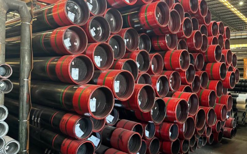
Integrating Weld Neck Flanges with Steel Pipe
Integrating weld neck flanges with steel pipes is particularly important for industries like petrochemical, oil and gas, and power generation. Weld neck flanges are exceptionally manufactured for high pressure and temperature applications, thus achieving maximum reliability and structural integrity. Smooth transfer of stress from the flange to the pipe is ensured by the long, tapered hub of the flange, enhancing the strength of the piping system.
Welding, in particular, full penetration butt welds, must be done very precisely to ensure the correct integration of the parts. The use of buttweld connections is preferred since it results in smooth internal flow and less turbulence due to full penetration welding. Usually, the materials used for the flanges and pipes need to be compatible; otherwise, galvanic corrosion and thermal expansion discrepancies will occur. For example, carbon steel flanges work well with carbon steel pipes, but higher grade stainless steel is used in corrosive environments due to better protective properties.
Key information from the latest industry standards shows that weld neck flanges are routinely made in accordance with ASME B16.5 for diameters up to 24 inches or ASME B16.47 for larger sizes. Commonly, the pressure classification ranges from 150 to 2500, thereby allowing diverse applications depending on the operational pressure range. In addition, the flange face type, be it raised face (RF) or ring type joint (RTJ), is selected depending on the seal and gasket requirements of the system.
During the installation phase, alignment is crucial to avoid excessive strain or offset, which can negatively impact the efficiency of the flange. Non-destructive testing (NDT), such as liquid penetrant inspection or radiographic testing, is recommended to check the weld and the assembled flange accuracy for quality and integrity after installation.
The incorporation of weld neck flanges into steel piping systems facilitates a highly strong and leak-free joint, which can withstand extreme operational conditions. When best practices such as the selection of the right materials and thorough inspection are followed, these flanges can sustain critical applications for years without failure.
Comparing Weld Neck Flanges to Other Flange Types

Differences Between Weld Neck and Slip-On Flanges
The design, application, and function of weld neck flanges and slip-on flanges show distinct differences.
- Design: Slash-on flanges have a geometric simplicity because they lack any extensions protruding from the pipe. Slip-on flanges “slide” over the pipe for securement and must be fillet welded. On the other hand, weld neck flanges have a longer tapering hub, exhibiting some degree of stress counteraction.
- Strength: The strongest flanges are those that are most difficult to manufacture, as in slip-on flanges. Slip-on flanges have less strength, giving them an edge in low-pressure applications compared to weld neck flanges, which are ideal for high-pressure applications.
- Installation: Less demanding in terms of geometry alignment and guide pins, makes the slip-on flange easier to weld in place.
- Cost: Affordability is mostly observed by gentle curves bumper: Slip-on flanges, where standard designs lead to low price brackets without compromising efficiency. Fabrications with heightening cuts and bevels rise towards accuracy hurdles, and ultimate weld neck flanges increase in price. Vendors take on the risk as constructions with greater tolerance make them better for reliability in high-pressure systems.
Using fewer resources, like space restrictions, makes slip-on flanges the all-rounders of less confrontational environments. They strive while weld neck flanges take on critical, trusted system applications.
Understanding the Long Weld Neck Flange
The long weld neck flange is a special type of flange useful in extremely high-pressure and temperature applications. It has an extended neck, unlike the typical weld neck flanges, which offer additional support and smooth stress distribution through the pipeline. This design mitigates the potential for fatigue while maximizing longevity in demanding conditions. Its sharp construction and dependable performance make it most suitable for pressure vessels, heat exchangers, and process piping, which are critical systems.
How the Raised Face Affects Performance
The RF design constitutes an important detail that improves the sealing efficiency of flanges. It supplies a greater area to compress the gasket in flange interfaces, which ensures tight sealing in high-pressure conditions. The raised face height is set in relation to the flange size and pressure class, normally between 1/16 inch for lower pressure classes and 1/4 inch for higher pressure ones. This configuration helps in more gasket deformation, which assures a good seal with thermal changes or stresses caused by vibrations.
A multitude of research has proven that RF flanges help to reduce the leakage risk due to the constant pressure on the gasket material throughout its life. For example, the ASME B16.5 standard flanges have softer, semi-metal, and full metal gaskets, and the raised face makes them more compatible with different operating parameters. The combination of the raised face and newer materials used for gaskets greatly improves reliability in cyclic pressurized and high-temperature systems. Collectively, these enhance the aging and high endurance piping systems, sustaining integrity longer and reducing critical operational failure risks.
Choosing the Right Weld Neck Flange for Your Piping System

Key Considerations: Size and Specification
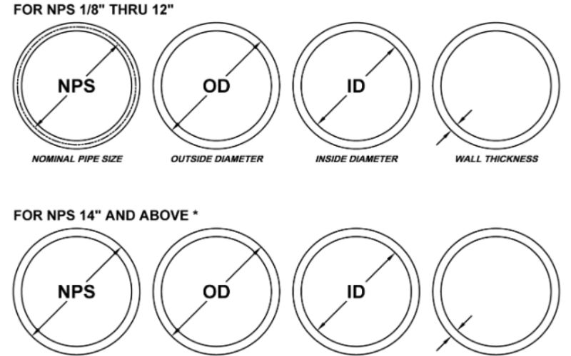
During the installation of piping systems, special attention should be paid to the sizing of weld neck flanges, crucial for ensuring the tight sealing of the systems as well as meeting specification standards. The flange size is usually determined by the nominal pipe size (NPS), meaning a 6 NPS would be compatible with industrial applications. Furthermore, the schedule or wall thickness is also important, meaning a schedule 40 would also be compatible.
Flanges have to comply with ASME B16.5 standards, which also cover the range of sizes between ½ inch and 24 inches and pressure classes of 150 to 2500. However, apart from the dimensions, the compatibility of materials is just as important. Carbon Steel is the metal of choice for many as their pressure and temperature requirements relative to the system. Moreover, Stainless Steel flanges also serve many purposes as they have superior resistance to oxidative damage; their use will prolong outage periods.
When selecting a flange, additional criteria such as temperature rating of the system and alignment of bolt holes also become crucial. A 300 class weld neck rated flange should be able to withstand 740 psi at 100°F, meaning pressure will have to be sustained at lower temperatures for higher ratings. Furthermore, congruous alignment of bolt holes will help provide even distribution of load, leading to decreased system strain.
The weld neck flange selected enhances the safety and efficiency of the piping system because the flange is accurate in dimensions, conforms to standards, and the appropriate environmental and operational factors are considered.
Fitting With Gaskets and Valves
In order to retain the structural integrity and functionality of a piping system, gaskets and valves must be fitted properly. Gaskets must be selected with regard to material compatibility, operating pressure, and temperature in order to provide a reliable seal and prevent leakage. Alignment of the flange faces with the gasket must be observed carefully to avoid misalignment, which may lead to uneven pressure distribution.
When installing a valve, ensure the valve type corresponds to the flow control requirements of the piping system. Proper orientation is critical, as any misalignment may cause undue stress on the valve, which hampers performance and flow regulation. Following the manufacturer’s instructions, as far as gasket and valve selection is concerned, aids in ensuring reliable long-term service.
Material Options: Stainless Steel vs Carbon Steel
Carbon Steel and Stainless steel are two widely used metals in different industries, which contain distinct properties that make them suitable for different applications.
- Carbon Steel: Carbon steel has numerous applications because they are quite cost-efficient and very strong. Since it is cheaper to produce, carbon metals perform best in situations where an anti-corrosive feature may not be needed, such as construction or tool manufacturing.
- Stainless Steel: Stainless steel does not rust and is prone to corrosion, making it perfect for areas that face chemicals, moisture, and extreme temperatures. These are quite durable, which means they require low maintenance. Since it is aesthetically pleasing, it is widely used in the food industry and in medical equipment.
Both of these metals have their advantages and disadvantages depending on the stainless steel’s durability, exposure to certain environments, and the need for cost efficiency.
Installation and Maintenance of Weld Neck Flanges

Steps for Proper Installation of Weld Neck Flanges
Examination of the flange and pipe
- Upon installation, assess the weld neck flange and the pipe for obvious defects, for example, cracks or dents. Check that all parts conform to the necessary guidelines and framework.
Align the Flange with Pipe
- Place the weld neck flange onto the pipe, ensuring it sits vertically and horizontally at the correct position. If the flange is not aligned properly, it may place undue strain on the connection, leading to leakage during operational use.
Tack weld the flange
- Place tack welds at several points around the flange for easier alignment before final welding. Doing this helps prevent the rotation of a joint alignment.
Perform the full weld
- Make a complete circumferential weld that strongly connects the anchor flange, which welds to the neck, then connects to the pipe. Follow proper welding procedures and make certain the diameter of the weld is homogeneous. This avoids areas of weakness in the joint.
Weld the joint and check for quality
- Upon completion of the welding process, have a visual inspection done, checking the alignment and cleaning the surface after inspection if necessary, and perform non-destructive evaluation of portions for verification. All connections must meet the level and condition of the standards of the design.
BOLT the connection of the flange
- Following the inspection and welding phases, set the working flange face against the other flange or component to be connected. Place the bolts through the holes and tighten them in a spiral until the predetermined radially adjusted tension is achieved.
Test for Leaks in the Assembly
- Perform hydrostatic or pneumatic tests as necessary to ensure the integrity of the flange connection, confirming that it is free of leaks and can withstand the required operational pressures.
Common Welding Techniques for Neck Flanges
The application, materials, and operational conditions impact the chosen welding technique for the neck flanges. Presented below are some of the most popular welding methods.
Shielded Metal Arc Welding (SMAW)
- SMAW or stick welding is one of the most popular techniques for welding neck flanges. Its versatility shines when used on carbon steel and low-alloy steel. This method uses rods with a flux-covered tip as a weld area protector, which prevents oxidation and contamination. SMAW sticks are effective in workshops and field applications and excels in high-pressure welds.
Gas Tungsten Arc Welding (GTAW)
- GTAW or TIG welding is the dominant procedure for welding non-ferrous materials like aluminum and titanium due to its elevated precision. GTAW employs a non-consumable tungsten electrode, providing superior control of the weld pool. It is very useful in places where the appearance of the weld matters, such as in the food and pharmaceutical industries. Industry statistics show that GTAW welds are relatively defect-free and have great tensile strength, fatigue strength, and other critical structural integrity benchmarks.
Submerged Arc Welding (SAW)
- This automated process works well for welding the large diameter neck flanges, and it is commonly applied in heavy engineering work. The technique of SAW consists of a continuously supplied wire electrode and the use of a powdered flux, which produces a protective slag. Because of the rapid deposition and deep penetration, SAW is best suited for high-strength welds in pipelines and pressure vessels. Research indicates productivity levels with SAW can be approximately 30% greater than with manual methods.
Gas Metal Arc Welding (GMAW)
- GMAW, or MIG welding, incorporates a continuously supplied wire electrode and shielding gas, and is therefore suited to mass production. In terms of efficiency, this semi-automatic method excels in welding medium to large neck flanges. Under well-defined parameters, GMAW ensures adequate bead appearance as well as high deposition. One particular advantage of this process is its ability to weld carbon steel; it shortens the time required for welding, therefore enhancing project turnaround.
Flux Cored Arc Welding (FCAW)
- FCAW is a type of GMAW that uses flux-filled tubular wire. This method is useful for thick, heavy plate materials, and under windy conditions, it maintains superior penetration. Because of its ability to maintain high-quality welds in adverse conditions, this method is widely accepted in construction and shipbuilding.
Factors Influencing Welding Technique Selection
For neck flanges, some of the most important parameters for selecting a welding method are type of material, flange diameter, operating pressure, and environmental conditions. For example, stainless steel neck flanges frequently require GTAW because of their precision and owing to corrosion; carbon steel flanges used in high-pressure systems, SMAW, or SAW might be advantageous because of their strength and efficiency. Certain industrial parameters like ASME B31.3 and ISO 15614 also aid in determining the suitability of the procedure and its applicability as per the technique requirements.
Maintaining Seal Integrity with Gaskets
Gaskets seal between flanges, preventing leakage and protecting the system from failure. To achieve optimal performance, the correct choice of gasket material with operating temperature, pressure, and media is critical. Adequate flange alignment and torque application, along with proper installation steps, increase seal integrity. Scheduled maintenance bolsters reliability through wear mitigation by inspecting and replacing gaskets.
Frequently Asked Questions (FAQs)
Q: What is a Weld Neck Flange?
A: A Weld Neck Flange or ‘WN Flange’ is a pipe flange provided for use in high-pressure systems involving high pressures and repeated bending cycles. It features a long, tapered hub, which provides an important reinforcement as it aids in transitioning smoothly from the flange thickness to the pipe or fitting.
Q: In what other ways does a weld neck flange differ from a slip-on flange?
A: A Weld Neck Flange is differentiated by the long, tapered hub, which provides reinforcement for high-pressure applications. Slip-On Flanges, on the other hand, are only piped from the outside and welded from the inner and outer portions in order to form a rigid structure. Unlike Weld Neck, Slip-On Flanges do not have joints that maintain the proportion of thickness joints.
Q: What are the commonly used materials for Weld Neck Flanges?
A: The common materials for Weld Neck Flanges include carbon steel, alloy steel, stainless steel, and nickel alloys. Specified Standards like A105 are frequently tailored for carbon steel welding neck flanges.
Q: What is the purpose of the long, tapered hub on a Weld Neck Flange?
A: The long, tapered hub on a Weld Neck Flange serves an essential function in providing an additional smooth transition from the thickness of the flange to the adjoining pipe or fitting. This helps to mitigate stress concentrations, which is especially helpful in systems with high pressure or repeatedly bending pipe sections.
Q: Why is it critical to consider the diameter of the Weld Neck Flange’s inside opening?
A: Consideration of the inside diameter of the Weld Neck Flange and the pipe or fitting is necessary to avoid turbulence within the fluid system. This also assists the system in preserving its effectiveness, improving dynamic performance, and reducing the possibility of system failure.
Q: Which industries use Weld Neck Flanges most often?
A: Weld Neck Flanges are used most often in industries where there is high pressure, extreme sub-zero temperatures, and repeated bending of parts. They are best used when a circular weld to join the pipe to the flange is needed for maximum strength.
Q: Can Weld Neck Flanges be used with different types of pipes?
A: Different types of pipes can be accommodated by Weld Neck Flanges as long as the flange’s diameter is congruent with the pipe or fitting’s inner diameter. With some modification to the flange design, they can also be used with pipes having varying wall thicknesses, like Schedule 40.
Q: Are there any alternatives to Weld Neck Flanges?
A: Weld Neck Flanges can be replaced with other flanges, such as lap joint flanges, socket weld flanges, or slip on flanges. The selection of a specific type of flange is determined by the other components of the piping system, along with the pressure and temperature conditions within the system.
Q: What standards and specifications apply to Weld Neck Flanges?
A: Weld Neck Flanges are primarily produced to comply with ANSI standards; their Workscope includes checking the dimensional, material, and performance requirements for various applications. Common specifications for carbon steel flanges are A105.
Reference Sources
1. Suppression of Weld Neck Flange Folding in Single-Step Forging
- Authors: Pedro Henrique Degasperi Escolastico et al.
- Publication Date: February 22, 2025
- Journal: International Journal on Interactive Design and Manufacturing (IJIDeM)
- Summary: This study focuses on resolving the folding of weld neck flanges that occurs during the single-step forging operation. The authors attempt to prevent the folding, which is a potential defect in the flange, from occurring. Even though specific methodologies are not presented in the excerpt, it is logical to assume that the research incorporates some experimental setups and analyses to validate the theories.
- Citation: (Escolastico et al., 2025)
2. A Comparative Study Between ASME B16.5 and EN1092-1 Weld Neck Flanges
- Authors: A. Bouzid, Sofiane Bouzid
- Publication Date: July 28, 2024
- Journal: Volume 1: Codes & Standards; Computer Technology & Bolted Joints
- Summary: This paper details a comparison between two standards, ASME B16.5 and EN 1092-1, regarding weld neck flanges pertaining to their integrity and leak tightness. The balance of different sizes and pressure ratings was studied with respect to rotational inertia as well as maximum and contact gasket stresses, bolt loads, and flanges. The authors provide a robust explanation of the differences between these two standards using analytical models, which are frequently utilized by experts in these fields.
- Citation: (Bouzid & Bouzid, 2024)
3. Failure Analysis Of A Weld Neck Flange Of The Discharge Piping Of An Ethylene Compressor In A Petrochemical Complex
- Authors: Okpala, N. Alexander
- Publication Date: February 17, 2012
- Journal: Global Journal of Research In Engineering
- Summary: This paper focuses on engineering failure design mistakes in the maintenance of the weld neck flange in a petrochemical facility and explores its repercussions in regard to design and maintenance. It is, however, readily available with a gap of less than five years to aid studies pertaining to weld neck flanges.
- Citation: (Okpala & Alexander, 2012)
4. Welding
5. Steel