Slip-on flanges are an important item in many industries that are easy to install yet also inexpensive. Or perhaps you are in the industries mentioned or even construction; these shall help you appreciate the value and function of such attachments to the system without weakening the system’s performance. In these discussions, the attention is focused on design and scope of slip-on flanges as well as the advantages coming from the construction of such flanges. Wherever you look at making your operations more efficient, logistic or assembly process easier or faster, or whether you are required to spend within mandated standards, this exhaustive article aims to provide you necessary information. Scroll down below to see how flange slip can revolutionize your business.
What is a Slip-On Flange?
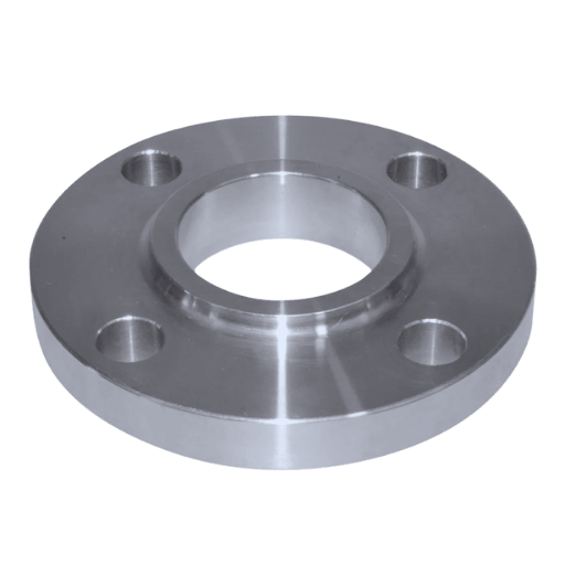
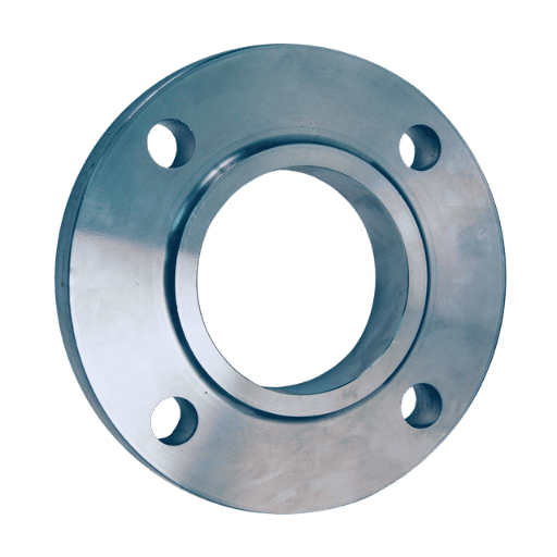
A slip-on flange is engineered to fit loosely over the terminal end of a pipe and subsequently be welded along the joint. The flange incorporates a short hub exhibiting an internal diameter that slightly exceeds the pipe’s outer diameter, facilitating straightforward alignment before the weld is deposited. Industry practice frequently favors the slip-on design because of its uncomplicated assembly, modest material expense, and suitability for low-pressure service. The joint permits minor angular adjustments during installation, thereby easing the otherwise tedious task of achieving perfect alignment in less-demanding applications.
Understanding the Flange Structure
A flange is a projecting ring of a component used to connect pipes, valves, pumps, and other elements, ensuring the addition of strength and making connections without any flange slip possible.
Applications in Pipe Systems
- Welds, unions, and threaded fittings create leak-free routes for liquid fuels, process waters, or compressed gases.
- Flanges double as fixtures for valves, strainers, and metering pumps, turning a simple pipe run into a responsive circuit.
- Handholes and inspection doors break the monotony of steel, inviting technicians to gauge, scrub, or document system health.
- Quick-disconnect couplings let crews swap out sections on short notice, minimizing downtime during last-minute repairs.
- Expansion loops and braided bellows cushion the pipe against heat surges and machine rumble, prolonging service life.
- Reducing flanges bridge the gap between schedule-40 pipe and oversized actuators, matching odd-ball dimensions without custom fab.
- PTFE or Inconel gaskets bite into serrated sealing faces, containing acid vapors and hydraulic spikes that would shred paper seals.
Advantages Over Other Flange Types
- The flange slip also allows for easy bolt hole alignment, making it even less time-consuming to install.
- Strength is essentially amplified where reinforced materials are used for high-performance applications.
- Usable with many pipe casing materials, including stainless steel, carbon steel, and any exotics.
- Accommodates designs depending on the presence or absence of complex pipe networks as well as systems that subject the piping process to different pressures and temperatures.
- It helps to connect tightly and adequately, thus minimizing the potential leak paths, and affordable approaches that can be used in standard piping systems as well as in other systems.
- It is completely wear and corrosion resistant, which makes it long-lasting.
- Little upkeep is required for the majority of components due to the heavy-duty construction and components.
- Letting the client work in a wide range of high-pressure conditions without performance or safety impairment.
- Meets relevant codes of practice such as ASME, ANSI, and ISO to promote use in cross-disciplinary industries.
How to Install a Slip-On Flange?
Preparation of the Pipe and Fitting
Skilled mechanics insist that sound preparation makes or breaks any slip-on-flange installation, and they’re usually right. A first step is a candid look at both pipe and flange cracks, scratches, or even a wobble, giving early warning of trouble. Next comes cleaning; a wire brush or quick solvent wipe chases off grease, grit, or rust, leaving bare metal ready to bond. If the pipe end looks rough-cut and bevel it until the leading edge meets whatever detail the drawings demand. Diameter matters, too; a snug match between the pipes’ outside measurement and the flanges’ inside circle keeps the joint from bending under strain. Just before the arc is struck, run one last check on dimensions and swivel the flange to line up with whatever equipment or pipeline it must join.
Welding Techniques for Slip-On Flanges
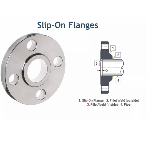
Flange slip-on joints have to be tight. This can be achieved by employing two fillet welds at both ends. One fillet is done on the inside of the flange slip pocket end, and another on the outer top end of the flange slip. The pipe is not thrust into the flange in excess. The welding process employed shall be dictated, however, by the application and the welding procedure specification available.
Ensuring Proper Gasket Alignment
Correctly positioning a gasket remains one of the simplest yet most overlooked steps in preventing flange leaks. Compatibility comes first: the material must survive the fluids, pressures, and temperatures it will face once the system starts up. Centering the gasket between the flanges allows compression to spread uniformly; any off-center placement risks concentrating stress in one narrow strip. A twisted or crooked install invites extrusion, excessive squirm, or a brand-new failure weeks before the next inspection. Before tightening, each sealing surface should be wiped spotless and checked for nicks, gouges, or warping. Dedicated tools-gasket pins, guide rings, or even scraps of rod-keeps the ring seated while the bolts go in, and that small extra effort often decides how long the joint will hold.
Materials Used for Slip-On Flanges
Choosing Between Stainless Steel and Carbon Steel
Deciding on whether carbon or stainless steel should be used in slip flange applications depends on the type of application in question. When it comes to high corrosion-prone environments such as Chemical processing and marine environments, I always prefer stainless steel. However, where there is a need for economy in the material and high load applications, I recommend such a carbon steel. My choice in all cases follows a series of judgments based on the operating conditions present, finances available, and the wear resistance of the element in the end.
Benefits of Raised Face Options
- Enhanced Sealing Ability: The focusing of the sealing pressure onto a smaller area of the gasket in the case of the raised base flanges contributes to the attainment of a more effective and secure seal.
- Gasket Versatility: They can accommodate almost all kinds of gaskets, including the softer forms and spiral wound gaskets for nearly any application.
- Pressure and Heat Tolerance: Designed for high-pressure, high-temperature systems because of the superior sealing capabilities.
- Ease of Assembly: The raised faces help in the alignment of the surfaces to be joined in the installation, reducing time and mistakes.
- Use in Industry: Those flanges have been in use for quite some time and are adopted as a standard to be incorporated into the existing pipe systems and installations in most industries.
- Longevity and Repair: Ensures durability over a suitable period, and in addition, corrosion does not take place very often with the proper selection of materials and good installation practices.
Considerations for High-Pressure Applications
- Material Selection: Opt for materials that possess superior tensile strength and can withstand stresses throughout use, thereby not failing.
- Sealing Efficiency: Ensure usage of the pressure-rated gaskets so as to curtail leakage and retain the positions of the contacts.
- Thermal Compatibility: Check whether all of the materials, fasteners, and gaskets, among other engineered systems, can survive the service temperature ranges without any significant wear and tear.
- Correct Method of Installation: Follow the exact torque values and other alignment instructions to prevent applying excessive forces or mispositioning the parts.
- In-service Examinations: Establish a regular service inspection regime for indicating creeping, fatigue, or stress corrosion cracking within the system of high pressure.
- Evaluation of Pressure Ratings and Capacity: Ensure that the various elements are within or over the rated operating pressure, and where necessary, hydrostatic and pneumatic tests are part of the program.
- Safety Measures: Install the relevant safety systems that shall address any possible risks from such an operation, considering the use of critical parts like pressure relief valves and emergency shutdown systems
What Are the Differences Between Slip-On Flange and Other Flanges?
Compared with Socket Weld Flanges
IP-on flanges tend to be budget-friendly, user-friendly, and well-matched to low- to moderate-pressure lines on the larger end of the pipe spectrum. In contrast, socket-weld flanges offer superior strength, practically eliminate leaks, and are the go-to choice when the service pressure soars and the pipe diameter shrinks.
|
Parameter |
Slip-On Flange |
Socket Weld Flange |
|---|---|---|
|
Pressure |
Low to moderate |
High |
|
Temperature |
Moderate |
High |
|
Pipe Size |
Large (up to 24″) |
Small (≤ 2″) |
|
Strength |
Lower |
Higher |
|
Installation |
Easier, dual welds |
Precise, single weld |
|
Cost |
Economical |
Higher |
|
Applications |
HVAC, plumbing |
Chemical, steam lines |
|
Material |
Carbon, stainless steel |
Alloy, stainless steel |
|
Durability |
Moderate |
High |
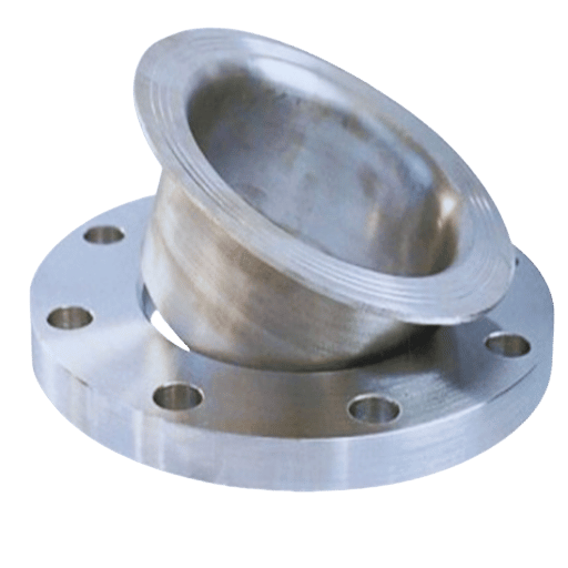
Understanding Lap Joint and Stub End Compatibility
The stub end and the lap joint flanges can be used together because the stub end and the pipe are joined using a butt weld while the lap joint flange slip over the stub, which has a radius to accommodate the raised flange allowing easy assembly and fastcenter.
Evaluating Flange Type Based on Pipe Size
Choosing the right flange for a given pipe diameter is rarely a simple checklist decision; engineers routinely weigh design pressure, service temperature, and the mechanical behavior of the base material. Each flange must match the nominal bore exactly if safety margins and reliable function are to be preserved on the line.
Flange Sizing Standards
Typically, flanges are dimensioned according to the standard measurements established by a group such as ASME (American Society of Mechanical Engineers). The following are related aspects worth mentioning:
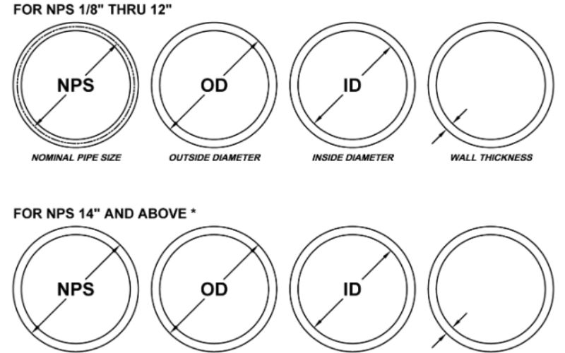
- Nominal Pipe Size (NPS): The nominal diameter of the pipe.
- Pressure Class: Such pressures, wearing 150, 300, 600, 900, and may rise to almost anything, represent the pressure range that the flange is designed to withstand.
- Outside Diameter (OD): This is the maximum diameter across the flange.
- Bolt Circle Diameter (BCD): Distance from center to center of the bolts along the circumference of the flange slip.
|
Nominal Pipe Size (NPS) |
Pressure Class 150 OD (in) |
Pressure Class 300 OD (in) |
Pressure Class 600 OD (in) |
|---|---|---|---|
|
2 |
6.00 |
6.50 |
6.65 |
|
4 |
9.00 |
9.50 |
10.75 |
|
6 |
11.00 |
11.50 |
14.00 |
|
8 |
13.50 |
13.88 |
15.88 |
Choosing the Right Flange Type
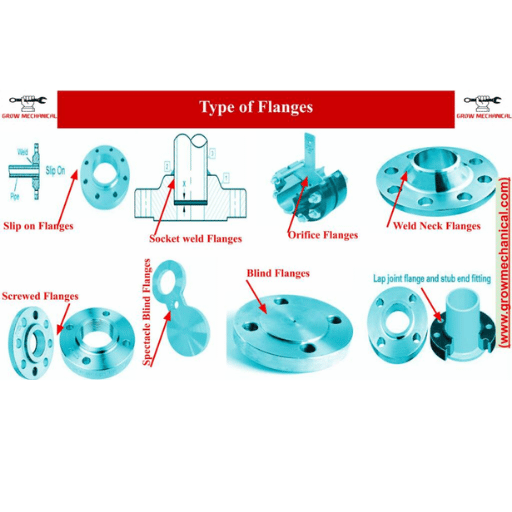
Deciding on a particular flange type, such as weld flange, slip welded neck flange, slip-on flange, and lap joint flange, usually depends on the size of pipes and their performance:
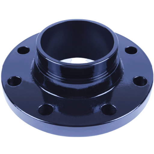
- Weld Neck Flanges: These flanges are best when the temperature and pressure are high and required to be equal to the inside bore or diameter of the pipe.
- Slip-On Flanges: Slip-on flanges are used for controlled low pressures and tend to be cheaper, especially when the pipe is smaller.
- Socket Weld Flanges: These flanges are generally utilized in small diameter piping systems where high pressure is involved, and a welded connection is needed.
- Lap Joint Flanges: Flanges that are utilized in applications where frequent assembling and dismantling is necessary. They are primarily utilized with butt-welded stub ends for assembling purposes.
Key Considerations
- Pipelines exceeding 24 inches in diameter often necessitate custom flanges; off-the-shelf configurations simply fall short.
- The choice of material-carbon steel, stainless steel, or an alloyed variant-depends heavily on factors such as corrosion exposure, temperature swings, and budget constraints.
- Compliance with benchmark specifications like ASME B16.5 or B16.47 remains essential for inter-system compatibility and baseline safety.
Careful pairing of flange style with pipe size, matched against the project brief, can enhance overall system resilience and curtail unplanned downtime.
Why Choose a Slip-On Flange for Your Project?
Cost-Effectiveness in Low-Pressure Systems
In case of low-pressure systems, a flange slip-on is a reasonably cheaper selection than any other because slip-on fittings are relatively easier to fit and thus less costly. Less welding is required as compared to other flange types in slip-on flanges, hence reducing both the working cost and the time required for a particular project. Another advantage of slip-on flanges is that it is very common and typically do not cost much, hence they are a very good option, especially in areas where pressure is not an issue. The installation is also simple, which lessens any trouble with aligning, which in turn makes the processes cost-efficient in these cases.
Ease of Installation for Piping System Maintenance
Whenever flanges need to be fitted into pipes, slip-on flanges have been a great boon, especially in maintenance jobs. Present data and opinions in the industry show that it is becoming more frequently observed in applications in industries that require rapid work and short downtimes. Slip-on flanges of the new generation are made more durable and accurate, made for easy installation with the already existing piping installations, due to the more advanced materials available and the better manufacturing processes.
A lot of professionals attempt to find affordable as well as ways that can withstand failure. Thus, slip-on flanges are capable of checking these boxes efficiently. Their ease of attachment reduces trouble during maintenance as these factors, such as unnecessary welding or a mispositioned joint are avoided and the facility remains functional almost always. Both productivity and adaptability make them a beneficial solution for today’s piping system maintenance.
Versatility in Class Ratings, Including Class 150
Slip-on Flanges have a high relevance to most of the class ratings, especially Class 150. It portrays the pressure-temperature performance of the flange, which enables incorporation into systems that harbour mild to moderate pressures. A wealth of applications utilize predominantly the class 150 or 150-pound slip flange due to its heavy usage and favorable economics, such as water supply and heating/air conditioning networks. They can easily cater to the requirements of a mixture of pipe diameters and even materials, which, of course, seems quite appropriate in industries where solid, yet very simple piping joints are needed.
Frequently Asked Questions (FAQs)
Q: What does a slip-on flask flange look like, and what is it’s/its main purpose in pipe fittings?
A: This type of pipe flange is designed to be slipped over a pipe and welded with the pipe; hence the name ‘slip-on’. It is used where the designed pipe needs to be linked to another pipe or equipment with an end connection. The installation of a slip-fit pipe flange makes it useful for low-pressure services.
Q: Why should I use a slip-on flange on low-pressure applications?
A: In low-pressure installations, slip-on flanges are cost and time-saving options due to easy fitting as well as centering ease. They easily seal and are cheaper than most usual flanges, such as weld and lap joints. These types of flanges are mainly advantageous when there will be repeated removal in the systems where they will be used.
Q: What determines the diameter size used in slip-on flanges?
A: The flange slip diameter is utilized to see whether it will be able to join the pipe, and that it is desired to be connected with. Remember that every flange must be applied with an outer pipe that corresponds to its inner size flange to fit properly. This size ensures adequate attachment capabilities and eliminates potential leaks.
Q: Which slip-on flanges are available in which sizes, and what is the typical size of a 2-inch joint?
A: Talk to the valve manufacturer to find out what sizes are avail for enlargers and how large the enlargers need to be. Where a 2-inch fitting exists, a matching slip-on flange of the same frame (external dimension) of the pipe has to be fitted. This is referred to in the ANSI B16.5 2 in 150 lb blind flange dimensions.
Q: Are there any restrictions on the materials used for producing slip-on flanges?
A: It is common for slip-on flanges to be made from materials such as steel, and steel slip, stainless steel 316L, which has a good corrosion rate. The material chosen will depend on pressure applications and environments.
Q: How are the slip-on and weld neck flanges connected differently?
A: The main difference between a slip-on and a weld neck flange is the method of connection. A slip-on flange slides over the end of the pipe and then is welded in place, while a weld neck flange has a section of material that is called the neck and is welded to the pipe. Most often, a weld neck flange can work with higher pressures than a compared slip-on flange.
Q: What role do bolt holes on slip-on flanges play in ensuring the solidity of the joint?
A: These holes on the slip-on flanges line up with the ones on the other flange or equipment in position so that the bolts may go through them as well and bolt the two together. This prevents loosening and moves the flange in, which is important, as it reduces the chances of failure because of the untightened joints.
Q: Did someone mention that there are very few pipe fitting types compatible with a slip-on flange?
A: No, there is no end to the types of pipes that can be attached using a slip-on flange, and hence, all types of pipes can be used, such as threaded and seamless pipes. On the other hand, they fit different types of •connection systems and are used by those components that need to be •assembled and disassembled many times.
Q: Are there any important principles that need to be followed when selecting slip-on flanges for low-pressure applications?
A: Certain aspects need to be taken into account when preparing a flange slip series with gaskets for a low-pressure application isolation purposes. Remember that the material, diameter, and style of the flange low pressure applications – the last two parameters are important. In order to save costs and prevent leakages, flanges must be suited to the external dimensions of the pipe using an appropriate material like steel slip.
Reference Sources
1. Title: Desirable Geometrical Configurations of the Web-Flange Splices for Enhancing the Frictional Slip Resistance of an I-Girder
- Authors: R. Sakura, Takashi Yamaguchi
- Publication Year: 2022
- Source: Proceedings of the IABSE Congress, Nanjing 2022
Key Findings:
- The paper dives into the slip tendencies of high-strength, friction-type bolts seated within I-girder assemblies.
- Elastic-plastic Finite Element Analysis threads through a range of web widths, flange depths, and staggered bolt layouts.
- Broadening bolt spacing while trimming the number of rows in the web splice noticeably lifts the measured friction force above conventional slip-resistance predictions.
- Those geometry tweaks hint at a straightforward route for engineers hoping to bolster connection durability without heavier hardware.
Methodology:
- Shell-and-beam FEA runs mapped out cooperative slip responses in dozens of splice prototypes (Sakura & Yamaguchi, 2022).
2. Title: Experimental Study into the Cooperative Slip-Bearing Limits of High-Strength Bolted-Frictional Girder Joints
- Authors: Ron Sakura, T. Yamaguchi, Yuhikus Aoki
- Publication Year: 2022
- Source: IABSE Symposium in Prague, 2022
Key Findings:
- The current study aims to determine the stiffness of bolted girder connections resisting revolving loads.
- The results disclosed that the slip failure in the tensile action and under compressive action, respectively, of bending members, occurs only during the moments of failure of the bolted group on the web.
- A formula was developed to predict the overall slip strength. The computed values are close to the experimental values.
Methodology:
- The research is descriptive and comparative as it describes the resistance and ductility properties of the girder under pure bending as shown in the work of (Sakura et al, 2022).
3. Topic: Analyzed specifics of non-linear analysis characteristics of steel screws in the bolted joints of a composite rotor
- Contributors: Author: Tao Li, et al.
- Year: 2021
- Journal: Journal of Mechanical Science and Technology
Main Purpose:
- The paper is devoted to the study of non-linearity in systems with bolted flanges subjected to combined rotation.
- The significance of obtaining an understanding of the dynamic characteristics to estimate the behaviour of bolted joints in use is also stressed.
- In order to avoid failure of mechanical components, the issue of slip modelling is particularly stressed.
Approach:
- The experimental and dynamic impact evaluation, looking particularly about the characteristics of bolted flange screws, had been performed (Li et al., 2021, p. 1841–1850).
4. Flange