Actualizado en agosto de 2026
Una calculadora de volumen de tuberías es una herramienta basada en una fórmula que obtiene el volumen cúbico a partir del diámetro interior y la longitud recta. La operación aritmética es sencilla; lo más complicado es elegir el diámetro correcto, mantener la compatibilidad entre unidades y saber cuándo el modelo cilíndrico deja de representar el sistema real. Si se utiliza correctamente, la fórmula siguiente indica cuánta agua puede contener una tubería cuando está ocupado todo su espacio interior; considera el agua dentro de la tubería como espacio ocupado, no como caudal. Esta guía muestra todos los datos de entrada y las conversiones para que pueda comprobar el resultado.
Resumen del cálculo
- Las designaciones nominales de las tuberías no son valores seguros para el diámetro.
- Con un error del 2 % en el diámetro interior, el volumen calculado varía un 4,04 % si la longitud se mantiene constante.
- Un galón estadounidense equivale a 231 pulgadas cúbicas o 3.785412 litros.
- Los codos, las válvulas, los depósitos, el flujo parcial y el gas comprimido requieren datos adicionales o un modelo distinto.
Datos básicos
| Modelo | Espacio interior circular, recto y lleno |
| Geometría necesaria | Diámetro interior D y longitud recta L |
| Fórmula del diámetro | V = πD²L/4 |
| Resultados métricos | mm³, cm³, litros, m³ |
| Resultados imperiales | in³, ft³, galones estadounidenses |
Calculadora de volumen de tuberías: empiece por el diámetro interior real
Para calcular el volumen de una tubería con fiabilidad, hay que partir del diámetro interior que puede ocupar el fluido, no de la designación nominal impresa en la tubería. Si mide el diámetro de una tubería, anote el valor, la longitud de la tubería o del tramo considerado, el origen de cada dato, el sistema de unidades y el resultado deseado. Si no se ha medido el diámetro interior, indique que el valor derivado de la serie es una geometría teórica de referencia.
El origen del diámetro importa porque la fórmula eleva ese dato al cuadrado. Incluso un pequeño error aumenta antes de aplicar la longitud o el factor de conversión. Anote la base del diámetro interior, aunque una hoja de cálculo lo denomine ID. La guía de estimación del volumen de tuberías de la US EPA considera teóricos los valores basados en dimensiones de normas de diseño y señala que los depósitos pueden reducir el diámetro interior útil durante el servicio.
Comprobación del diámetro nominal y el real
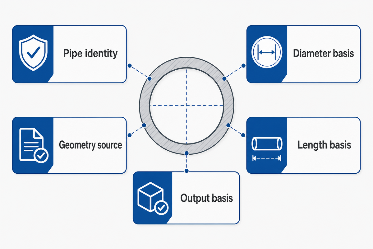
La comprobación del diámetro nominal y el real es una verificación de cinco campos que registra cómo se obtuvo el diámetro usado por la calculadora antes de dar por válido el resultado.
| Campo de comprobación | Qué registrar | Decisión |
|---|---|---|
| Identificación de la tubería | Norma, material, NPS o DN y serie/clase | Permite identificar la familia de referencia correcta |
| Base del diámetro | ID medido, plano certificado o ID derivado | Se prefiere el ID medido para calcular la capacidad física |
| Origen de la geometría | Registro de medición, revisión del plano o página de dimensiones | Permite auditar el resultado |
| Base de la longitud | Longitud recta por el eje e inclusión de los extremos | Evita solapamientos o tramos omitidos |
| Base del resultado | Litros, m³, galones estadounidenses o ft³ | Determina la ruta de conversión final |
La hoja de cálculo debe mantener separados los campos de la tubería y de la longitud para que quienes revisen el cálculo puedan rastrear cada dato.
Introducir «2 pulgadas» porque la tubería es NPS 2 omite tanto el espesor de pared como la convención de tamaño nominal. Este atajo solo puede servir para una estimación aproximada si se indica claramente su incertidumbre.
Fórmula del volumen de una tubería: V = πD²L/4
La fórmula del volumen de una tubería es la ecuación del cilindro expresada mediante el diámetro interior: V = πD²L/4. Eleve al cuadrado el diámetro interior, multiplíquelo por la longitud recta y por π, y divida el resultado entre cuatro. El diámetro y la longitud deben expresarse en unidades compatibles; por tanto, el primer resultado estará en milímetros cúbicos, metros cúbicos, pulgadas cúbicas o pies cúbicos.
La guía del NIST sobre circunferencia, área y volumen expresa el volumen de un cilindro como 0,7854 × diámetro × diámetro × altura y recomienda utilizar la misma unidad para todas las dimensiones. Para calcular el volumen, use el área de la sección transversal interior; el área de la superficie de la tubería responde a otra pregunta. La expresión πD²L/4 representa la misma relación, ya que π/4 equivale aproximadamente a 0.785398, y el procedimiento paso a paso que se presenta a continuación explicita la geometría.
| Símbolo | Significado | Regla para los datos de entrada |
|---|---|---|
| V | Volumen interior | Se expresa inicialmente en unidades cúbicas |
| π | Constante del círculo | Mantenga la precisión de la calculadora hasta el final |
| D | Diámetro interior | No sustituya el OD ni el tamaño nominal sin indicarlo |
| Yo | Longitud recta de la tubería | Use la misma unidad base que para D |
| o | Radio interior, D/2 | La fórmula alternativa es V = πr²L |
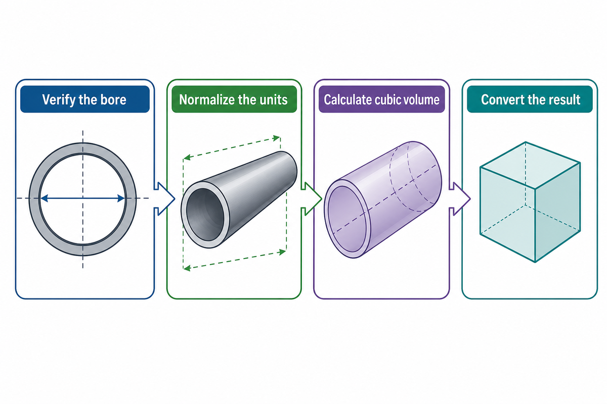
- Verifique el diámetro interior: registre el ID medido o identifique claramente un ID teórico vinculado a una fuente.
- Unifique las unidades: convierta el diámetro y la longitud a una unidad base compatible.
- Calcule el volumen cúbico: evalúe πD²L/4 sin redondeos intermedios.
- Convierta el resultado: transforme el valor cúbico final a litros, m³, galones estadounidenses o ft³.
Conserve al menos una cifra decimal más de la que necesite el informe final. Redondear el diámetro en pulgadas a pies antes de elevarlo al cuadrado puede alterar el resultado más que redondear el volumen final.
Tamaño nominal de tubería, diámetro exterior y diámetro interior

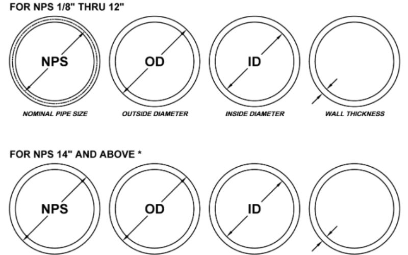
El tamaño nominal de tubería identifica una familia de tuberías normalizada; no indica directamente el diámetro interior. El diámetro exterior describe el contorno de la tubería, el espesor de pared ocupa material a ambos lados y el diámetro interior se obtiene mediante ID = OD − 2t. El ID obtenido de una tabla sigue siendo teórico hasta que se mide la tubería concreta.
Esta distinción explica por qué, en la sección sobre la fórmula, D se definió como el diámetro interior real o como un valor teórico explícito, y no como una designación nominal.
El ámbito de aplicación de B36.10 de ASME establece la normalización dimensional de las tuberías de acero forjado. ASTM precisa aún más el límite de medición: la nota 2 del ámbito de A53/A53M-24 indica que el espesor de pared nominal es una designación y que el espesor real puede ser mayor o menor.
También hay que verificar directamente el estado de la edición. La portada oficial de B36.10 identifica una revisión de 2022, mientras que el etiquetado público de los productos puede estar desactualizado; que haya una próxima edición prevista no demuestra que se haya publicado. Verifique la edición adquirida para el proyecto en lugar de deducir que está vigente a partir de una fecha indicada en una página.
Los cálculos de tuberías suelen fallar cuando se introduce el tamaño nominal en lugar del diámetro interior real requerido.
Un procedimiento útil consiste en consultar una tabla actual de tamaños de tubería, confirmar la tabla de series de tubería aplicable, obtener un ID de referencia y sustituirlo después por el de un plano aprobado o una medición cuando el volumen determine las operaciones de lavado, dosificación de productos químicos, toma de muestras o inventario.
- Registre la norma aplicable a la tubería y su edición.
- Mida el ID cuando importe la capacidad física.
- Indique que el ID derivado es una geometría teórica.
- Mantenga el OD, el espesor de pared y el ID en un único sistema de unidades.
- Introducir NPS como si fuera el ID medido.
- Usar el diámetro exterior en la fórmula del volumen.
- Transferir dimensiones entre normas sin comprobarlas.
- Usar la serie como atajo para determinar la presión nominal.
Conversión de unidades: litros, m³, galones estadounidenses y pies cúbicos
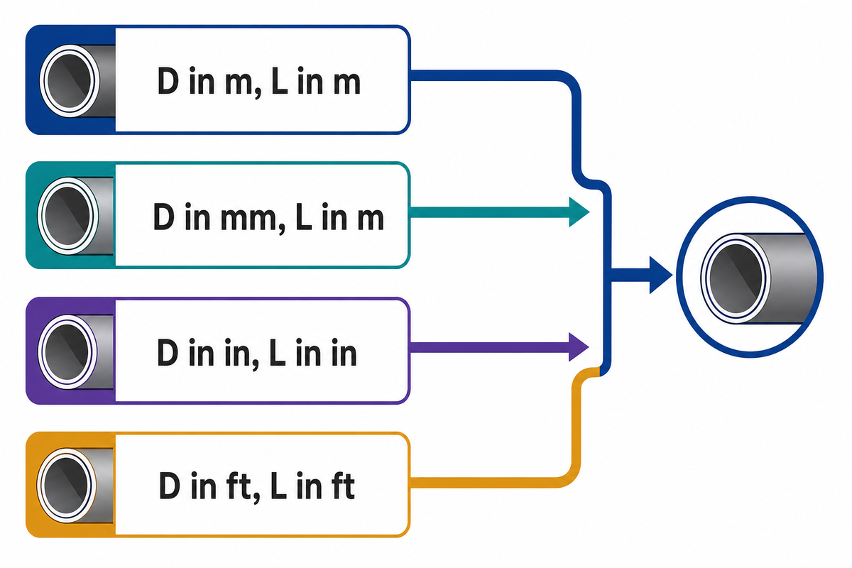
Para convertir unidades de forma segura, primero convierta las dimensiones geométricas, calcule el volumen en una única unidad cúbica y convierta el volumen final una sola vez. Tanto en el sistema métrico como en el imperial, cada dato de entrada debe llevar su unidad explícita, en lugar de depender de la unidad predeterminada del software. Si el diámetro de la tubería está en pulgadas, la longitud debe estar en pulgadas o convertirse de forma exacta; no mezcle pulgadas y pies en D²L.
La tabla de conversión del apéndice B.8 del NIST indica que 1 in³ = 1,638706 × 10⁻⁵ m³, 1 US gal = 3,785412 L y 1 L = exactamente 0,001 m³. Estos factores se mantienen hasta presentar el resultado final.
Para quienes buscan «calculadora de volumen de tuberías en m3», es necesario convertir ambas dimensiones geométricas a metros antes de aplicar la fórmula. Para calcular el volumen de una tubería en galones, mantenga compatibles las unidades imperiales de las dimensiones y divida el volumen final en pulgadas cúbicas entre 231.
Matriz de conversión de unidades
La matriz de conversión de unidades muestra una ruta de cálculo completa cada vez para evitar mezclar pulgadas y pies o milímetros y metros en D²L.
| Unidades de entrada | Resultado cúbico | Resultado final | Límites / No apto para |
|---|---|---|---|
| D en m, L en m | m³ | m³ directamente | No introduzca D en mm |
| D en m, L en m | m³ | × 1.000 = L | Los litros son solo una conversión final |
| D en mm, L en mm | mm³ | ÷ 1.000.000 = L | Poco práctico para tramos muy largos |
| D en mm, L en m | Use V(L) = πD²L/4,000 | L directamente | La fórmula incluye el factor para unidades mixtas |
| D en cm, L en cm | cm³ | ÷ 1.000 = L | Confirme que ninguna de las dos dimensiones esté en mm |
| D en in, L en in | in³ | ÷ 231 = US gal | Galones estadounidenses, no imperiales |
| D en in, L en ft | Convierta L × 12 a in | in³ o US gal | No redondee D ÷ 12 antes de elevarlo al cuadrado |
| D en ft, L en ft | ft³ | ft³ directamente | Convierta primero el diámetro de forma exacta |
| D en in, L en in | in³ | × 1,638706 × 10−2 = L | Conserve la precisión de la conversión |
La guía de unidades de agua de Oklahoma State University también advierte que sustituir unidades de caudal por unidades de volumen puede dar resultados que no parezcan claramente erróneos. Por tanto, las unidades deben figurar junto a cada dato de entrada y resultado, no solo en el encabezado de la hoja de cálculo.
Tres ejemplos resueltos y verificados, capacidad por unidad de longitud y varios tramos
Los ejemplos resueltos de volumen de tuberías deben mostrar el origen de los datos, la unificación de unidades, el cálculo cúbico y la conversión final. Los tres ejemplos siguientes abarcan un tubo métrico, una conversión de pulgadas y pies y una referencia geométrica teórica para una tubería NPS 2 de acero. En todos los cálculos se pospone el redondeo hasta obtener el volumen final que se presenta.
A continuación, las rutas de conversión anteriores se aplican en tres cálculos reproducibles paso a paso.
Ejemplo 1: ID de 50 mm en 12 m
En un ejemplo de mantenimiento resuelto, el volumen de agua que se necesita se encuentra dentro de un tramo recto de 12 m con un diámetro interior medido de 50,0 mm. Convierta 50,0 mm a 0,0500 m y calcule V = π × 0.0500² × 12 ÷ 4 = 0,0235619 m³. Al multiplicar por 1.000 se obtienen 23,56 L.
Ejemplo 2: ID de 4 in en 25 ft
Para una hoja de cálculo de lavado, los datos son un ID medido de 4.000 in y 25,0 ft de tubería recta. Convierta la longitud a 300 in. A continuación, V = π × 4.000² × 300 ÷ 4 = 3,769.91 in³. Este es el volumen en pulgadas cúbicas. Divida entre 231 para obtener 16.32 US gal, o entre 1.728 para obtener 2,182 ft³.
Ejemplo 3: geometría de referencia para NPS 2 Schedule 40
La página de ASTM A106 Grade B aporta contexto comercial. Este ejemplo utiliza por separado las dimensiones de referencia teóricas de NPS 2 publicadas para clientes por Baling Steel: 2.375 in de OD y un espesor de pared nominal de 0.154 in, que dan un ID = 2.375 − 2 × 0.154 = 2.067 in. Para 20 ft, el resultado calculado es 3.486 US gal o 13,20 L.
Aquí importa el origen de cada dato: se utilizan las celdas de dimensiones publicadas tras contrastarlas, mientras que se excluyen las afirmaciones no relacionadas sobre presión, certificación y producción de las páginas comerciales. El contraste también reveló datos de capacidad contradictorios en una página de calculadora con una puntuación alta; por eso, todos los resultados numéricos de esta guía para calcular el volumen de tuberías de acero se volvieron a calcular con πD²L/4 en lugar de copiarse de una tabla de volumen de tuberías.
| Ejemplo | Geometría | Resultado cúbico | Resultado convertido |
|---|---|---|---|
| Métrico | ID de 50,0 mm × 12,0 m | 0,0235619 m³ | 23,56 L |
| Imperial | ID de 4.000 in × 25,0 ft | 3,769.91 in³ | 16.32 US gal |
| Referencia NPS 2 | ID de 2.067 in × 20,0 ft | 805.35 in³ | 3.486 US gal |
Capacidad por pie y hoja de cálculo para varios tramos
Para varios tramos rectos, calcule el factor de volumen por pie de tubería para cada ID verificado. La referencia NPS 2 Schedule 40 anterior tiene una capacidad de 40.267 in³/ft, 0.1743 US gal/ft o 0,6599 L/ft. Este volumen de agua es proporcional a la longitud recta verificada. Doce pies con ese ID de referencia más ocho pies con el ID de referencia Schedule 80 suman 12 × 0.174317 + 8 × 0.153396 = 3.319 US gal.
| Tramo | ID verificado | Longitud | Factor de conversión | Volumen |
|---|---|---|---|---|
| A | 2.067 in | 12 ft | 0.174317 US gal/ft | 2.092 US gal |
| B | 1.939 in | 8 ft | 0.153396 US gal/ft | 1.227 US gal |
| Total de tubería recta | Se conservan los ID por separado | 20 ft | Sin promediar | 3.319 US gal |
| Componentes | Codos, tes y válvulas | N / A | Use el volumen verificado del componente | Sume por separado |
La guía de la EPA señala que los componentes pequeños introducen errores si no se incluyen en un modelo de tubería recta. No convierta la longitud por el eje de un codo en una longitud equivalente de cilindro recto, salvo que un método aprobado defina expresamente esa aproximación.
Schedule 40 frente a 80: regla de sensibilidad de la entrada D²
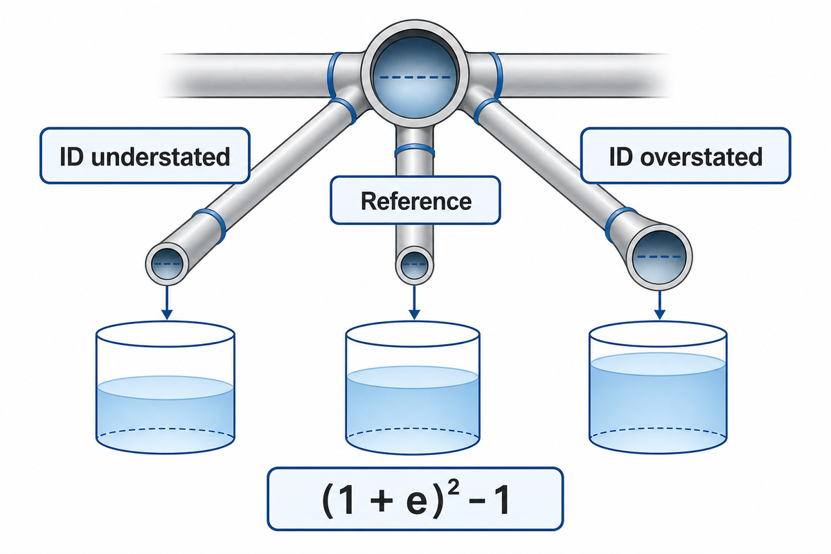
La regla de sensibilidad de la entrada D² establece que el volumen calculado varía con el cuadrado del valor del diámetro interior utilizado. Si la longitud se mantiene constante, un error relativo de diámetro e cambia el volumen en (1 + e)² − 1. La regla es exacta para el modelo cilíndrico del NIST, pero no constituye un certificado de tolerancia de fabricación.
Con el mismo OD de referencia para NPS 2, el ID de Schedule 40 es 2.067 in y el de Schedule 80 es 1.939 in. Su relación de volúmenes es (1.939 ÷ 2.067)² = 0.87998, por lo que la geometría de referencia Schedule 80 tiene aproximadamente un 12,00 % menos de capacidad que la referencia Schedule 40 para la misma longitud recta.
| Caso de entrada | Variación del diámetro | Variación del volumen calculado | Límites / No apto para |
|---|---|---|---|
| ID infravalorado | −5% | −9.75% | No es un supuesto de tolerancia |
| ID infravalorado | −2% | −3.96% | Compruebe el método de medición |
| ID infravalorado | −1% | −1.99% | Solo con longitud constante |
| Referencia | 0% | 0% | Solo es tan fiable como el dato de entrada |
| ID sobrevalorado | +1% | +2.01% | No incluye el error de longitud |
| ID sobrevalorado | +2% | +4.04% | No incluye la ovalidad |
| ID sobrevalorado | +5% | +10.25% | No incluye los depósitos |
| Ref. NPS 2 Sch 40 | ID de 2.067 in | 0.1743 US gal/ft | Geometría nominal teórica |
| Ref. NPS 2 Sch 80 | ID de 1.939 in | 0.1534 US gal/ft | Geometría nominal teórica |
Cadena de errores de capacidad
La cadena de errores de capacidad sigue este recorrido: designación nominal → espesor de pared de referencia → ID derivado → geometría elevada al cuadrado → conversión de unidades → resultado redondeado.
Hay una falsa precisión cuando el resultado final tiene tres decimales, pero el primer dato de la cadena es solo una designación nominal. Compruebe la cadena de izquierda a derecha: verifique la identidad y la geometría, calcule sin redondear antes de tiempo, convierta una vez y muestre solo la precisión que justifican los datos de entrada.
El volumen estático de una tubería no es el caudal, el tiempo de vaciado ni el peso del fluido
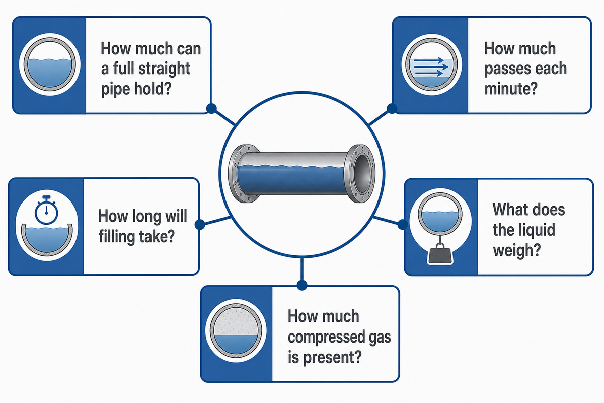
El volumen estático de una tubería mide el espacio interior y se expresa en unidades como litros o galones. El caudal mide la cantidad de fluido por unidad de tiempo; para calcular el peso del agua se necesita la densidad, y para determinar cuánto se tarda en llenar o vaciar la tubería hace falta una relación entre tiempo y caudal. El inventario de gas comprimido también requiere datos de presión, temperatura y comportamiento del gas.
La información de Oklahoma State University sobre medición del agua distingue el agua en reposo del agua en movimiento. Esto evita un error habitual de categoría: dividir los galones entre un tiempo supuesto y llamar caudal del sistema al resultado, sin datos de velocidad, presión, curva de la bomba, posición de la válvula, elevación o pérdidas. El peso del agua requiere un cálculo de densidad aparte, y el volumen de cualquier grifo o accesorio debe añadirse como componente.
| Pregunta | Modelo | Datos adicionales |
|---|---|---|
| ¿Cuánto puede contener una tubería recta llena? | V = πD²L/4 | ID y longitud verificados |
| ¿Cuánto fluido pasa cada minuto? | Q = área × velocidad | Velocidad o caudal medido |
| ¿Cuánto se tarda en llenar? | tiempo = volumen ÷ caudal | Un caudal fiable |
| ¿Cuánto pesa el líquido? | masa = densidad × volumen | Densidad del fluido en las condiciones indicadas |
| ¿Cuánto gas comprimido hay? | Cálculo del estado del gas | Presión absoluta, temperatura y modelo del gas |
El análisis de Ray Hardee en Pumps & Systems refuerza una conclusión general: para predecir el comportamiento de una tubería se necesitan el diámetro real y datos del sistema, no solo una designación nominal y una fórmula.
Límites de precisión y casos en que falla el modelo cilíndrico

La geometría cilíndrica permite estimar el espacio interior circular, recto y lleno para la planificación. Debe corregirse o sustituirse si el diámetro interior está parcialmente lleno, no es circular, está deformado, revestido o incrustado, o resulta difícil de medir; si los componentes tienen un peso importante en el cálculo; o si se necesita el volumen calibrado en condiciones de operación en lugar de la capacidad geométrica.
Estos límites amplían la elección del modelo descrita en la sección anterior: la fórmula del cilindro lleno por sí sola no permite determinar el caudal, el inventario de gas comprimido ni la capacidad con la tubería parcialmente llena.
Matriz de aplicabilidad de los cálculos
La matriz de aplicabilidad del cálculo asigna diez situaciones de tubería a las opciones de usar, usar con reservas o no usar antes de introducir el primer dato. Puede calcular un circuito hidrónico recto de climatización por tramos, pero no contempla volúmenes desconocidos de componentes ni tuberías parcialmente llenas.
| Condición | Decisión | Acción necesaria | Límites / No apto para |
|---|---|---|---|
| Recta, llena, circular y con diámetro interior medido | Usar | Aplicar πD²L/4 | Aun así, excluye los componentes |
| Varios tramos rectos | Usar por tramos | Calcular cada diámetro interior y sumar los resultados | No promediar diámetros interiores distintos |
| Diámetro interior deducido del Schedule | Usar con reservas | Indicar que es una referencia teórica | No es una medición de la tubería suministrada |
| Codos, tes y válvulas | Usar con reservas | Añadir los volúmenes verificados de los componentes | Sustituirlos por tramos rectos puede inducir a error |
| Incrustaciones o depósitos de corrosión | Medir | Determinar el diámetro interior efectivo | El diámetro interior de referencia puede sobreestimar la capacidad |
| Revestimiento interior o recubrimiento interno | Usar con reservas | Usar el diámetro interior tras el revestimiento | El diámetro interior nominal del acero no es suficiente |
| Tubería horizontal parcialmente llena | No usar por sí sola | Usar la geometría de un segmento circular | Se necesitan la profundidad de llenado y la orientación |
| Diámetro interior ovalado, aplastado o flexible | No usar por sí sola | Medir la sección transversal real | Un solo diámetro no permite describir el área |
| Inventario de gas comprimido | Modelo no adecuado | Aplicar un método basado en el estado del gas | El volumen geométrico es solo uno de los datos de entrada |
| Trabajos de metrología o transferencia de custodia con calibración | Nivel de precisión inadecuado | Usar mediciones calibradas y analizar la incertidumbre | Puede requerir correcciones de temperatura y presión |
Las directrices de la EPA advierten específicamente que los depósitos de corrosión pueden estrechar el diámetro interior y que los componentes pequeños no incluidos en el modelo aumentan el error del volumen final. Para trabajos que requieren mayor precisión, un estudio revisado por pares de 2024 sobre un probador de tuberías segmentado mide el diámetro y la longitud de cada tramo y realiza un análisis formal de la incertidumbre. La incertidumbre expandida del 0,012 % que se indica corresponde a ese aparato calibrado, no a un cálculo corriente de un artículo.
- Planificar el volumen de lavado de tramos rectos verificados
- Comparar capacidades teóricas para una longitud fija
- Crear una hoja de cálculo transparente por pie o por metro
- Transferencia de custodia o medición con equipos calibrados
- Análisis hidráulico de una tubería parcialmente llena
- Inventario de gas comprimido en funcionamiento
- Sistemas en los que predominan componentes o depósitos desconocidos
Añadir decimales no compensa un diámetro interior sin verificar: primero, compruebe el origen de los datos de entrada; después, calcule πD²L/4 y, si la tubería no es recta, está llena y es circular, elija otro modelo.
Preguntas frecuentes
Estas preguntas frecuentes responden a las dudas más habituales sobre la fórmula, los litros, el material, el caudal, la precisión y el cálculo de varios tramos, sin alterar los límites del modelo.
¿Cómo se calcula el volumen de una tubería?
Para una tubería recta, llena y circular, use V = πD²L/4: eleve al cuadrado el diámetro interior real, multiplíquelo por una longitud compatible y por π, y divida el resultado entre cuatro antes de convertir las unidades.
¿Cómo calculo el volumen de una tubería en litros?
Calcule el volumen en metros cúbicos y multiplíquelo por 1.000 litros por m³, o use el diámetro en milímetros y la longitud en metros en V(L) = πD²L/4,000, sin redondear antes en ningún paso.
¿El material de la tubería cambia el volumen total?
El material de la tubería no interviene por sí mismo en la ecuación del cilindro: el volumen depende de la geometría, y el material solo cambia la capacidad si afecta al espesor de pared o al diámetro interior final.
¿Qué diferencia hay entre el volumen de una tubería y el caudal?
El volumen de una tubería es el espacio interior, medido en litros o galones; el caudal es la cantidad que pasa por un punto por unidad de tiempo y requiere otros datos del sistema.
¿Qué precisión tiene el cálculo del volumen de una tubería?
La precisión depende más de que el diámetro interior y la longitud recta estén verificados y el modelo sea válido que de los decimales mostrados, ya que las variaciones de fabricación, los depósitos, los accesorios y el nivel de llenado pueden ser las principales fuentes de incertidumbre.
¿Puedo calcular juntos varios tramos de tubería?
Calcule cada tramo recto con su propio diámetro interior y longitud verificados, sume los volúmenes de los tramos y añada por separado los volúmenes verificados de codos, válvulas, reductores o caudalímetros.
Convierta la estimación en una especificación de tubería trazable
Revise los datos de entrada antes de solicitar la tubería o confirmar el volumen de lavado. La información publicada por Baling Steel sobre la empresa y sus proyectos puede ayudar a los equipos de compras a preparar la parte comercial de esa revisión.
Consultar referencias de proyectos →Alcance de esta guía de cálculo
Las afirmaciones sobre fórmulas y conversiones se basan en fuentes del NIST, la EPA, universidades, organismos de normalización y publicaciones revisadas por pares. Las páginas de Baling Steel solo aportan información atribuida sobre productos y la empresa; no se consideran pruebas independientes de la fórmula, la capacidad medida ni la idoneidad para aplicaciones de ingeniería. Más información sobre Baling Steel y sus recursos publicados sobre calidad e inspección. Esta estimación educativa no constituye una aprobación de ingeniería para un proyecto ni un certificado de medición calibrada.
Artículos relacionados
- Tabla de dimensiones de tuberías: relación entre NPS, diámetro exterior y espesor de pared
- Tabla de Schedule de tuberías: comparación de los valores de referencia del espesor de pared y el diámetro interior
- Recursos de Baling Steel sobre calidad, inspección y suministro
- Acerca de Baling Steel: ámbito de la empresa y sus productos
Referencias y fuentes
- Circunferencia, área y volumen National Institute of Standards and Technology
- Guía de la herramienta para estimar volúmenes de instalaciones de fontanería US Environmental Protection Agency
- Alcance público de ASME B36.10M American Society of Mechanical Engineers
- Alcance público de ASTM A53/A53M-24 ASTM International
- Guía del NIST sobre el SI, apéndice B.8 National Institute of Standards and Technology
- Unidades de medida del agua y factores de conversión Oklahoma State University Extension
- Cálculo de la pérdida de carga en una tubería Pumps & Systems, Ray Hardee, P.E.
- Medición del volumen e incertidumbre en un probador de tuberías segmentado Sensors, 2024